AUTOMATIC TRANSMISSION SYSTEM, Diagnostic DTC:P0748

| DTC Code | DTC Name |
|---|---|
| P0748 | Pressure Control Solenoid "A" Electrical (Shift Solenoid Valve SL1) |
DESCRIPTION
Shifting from 1st to 6th gear is performed in combination with "ON" and "OFF" operation of the shift solenoid valves SL1, SL2, S1, S2, S3, S4 and SR which is controlled by the ECM. If an open or short circuit occurs in any of the shift solenoid valves, the ECM controls the remaining normal shift solenoid valve to allow the gears to be shifted smoothly.
| DTC No. | Detection Item | DTC Detection Condition | Trouble Area | MIL | Memory |
|---|---|---|---|---|---|
| P0748 | Pressure Control Solenoid "A" Electrical (Shift Solenoid Valve SL1) | The ECM checks for an open or short in the shift solenoid valve SL1 circuit while driving and shifting between 4th and 5th gear. (1-trip detection logic)
|
|
Comes on | DTC stored |
MONITOR DESCRIPTION
This DTC indicates an open or short in the shift solenoid valve SL1 circuit. The ECM commands gearshift by turning the shift solenoid valves "ON/OFF". When there is an open or short circuit in any shift solenoid valve circuit, the ECM detects the problem, illuminates the MIL and stores this DTC. The ECM performs the fail-safe function and turns the other normal shift solenoid valves "ON/OFF". (In case of an open or short circuit, the ECM stops sending current to the circuit.)
While driving and shifting between 4th and 5th gear, if the ECM detects an open or short in the shift solenoid valve SL1 circuit, the ECM determines there is a malfunction.
WIRING DIAGRAM
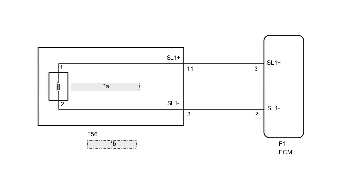
| *a | Shift Solenoid Valve SL1 |
| *b | Transmission Wire |
CAUTION / NOTICE / HINT
Note
Perform registration and/or initialization when parts related to the automatic transmission are replaced.
Tech Tips
-
The shift solenoid valve SL1 is turned on/off normally when the shift lever is in the D position:
ECM commanded gear 1st 2nd 3rd 4th 5th 6th Shift solenoid valve SL1 OFF OFF OFF OFF ON ON
PROCEDURE
-
INSPECT TRANSMISSION WIRE (SHIFT SOLENOID VALVE SL1)
-
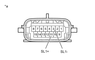
*a Component without harness connected
(Transmission Wire)
Disconnect the transmission wire connector from the transmission.
-
Measure the resistance according to the value(s) in the table below.
Standard Resistance Tester Connection Condition Specified Condition 11 (SL1+) - 3 (SL1-) 20°C (68°F) 5.0 to 5.6 Ω -
Measure the resistance according to the value(s) in the table below.
Standard Resistance (Check for short) Tester Connection Condition Specified Condition 11 (SL1+) - Body ground Always 10 kΩ or higher 3 (SL1-) - Body ground Always 10 kΩ or higher Result Proceed to OK NG
NG 
INSPECT SHIFT SOLENOID VALVE SL1 Click here
OK 
-
-
CHECK HARNESS AND CONNECTOR (TRANSMISSION WIRE - ECM)
-
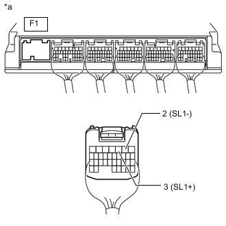
*a Rear view of wire harness connector
(to ECM)
Connect the transmission connector to the transmission.
-
Disconnect the F1 connector from the ECM.
-
Measure the resistance according to the value(s) in the table below.
Standard Resistance Tester Connection Condition Specified Condition F1-3 (SL1+) - F1-2 (SL1-) 20°C (68°F) 5.0 to 5.6 Ω -
Measure the resistance according to the value(s) in the table below.
Standard Resistance (Check for short) Tester Connection Condition Specified Condition F1-3 (SL1+) - Body ground Always 10 kΩ or higher F1-2 (SL1-) - Body ground Always 10 kΩ or higher Result Proceed to OK NG
OK 
REPLACE ECM Click here
NG
REPAIR OR REPLACE HARNESS OR CONNECTOR
-
-
INSPECT SHIFT SOLENOID VALVE SL1
-
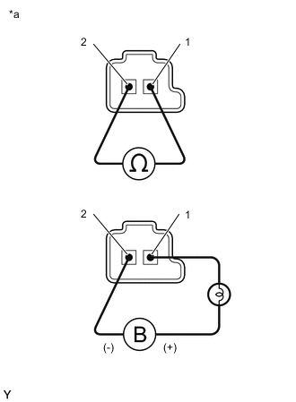
*a Shift Solenoid Valve SL1 Remove the shift solenoid valve SL1.
-
Measure the resistance according to the value(s) in the table below.
Standard Resistance Tester Connection Condition Specified Condition 1 - 2 20°C (68°F) 5.0 to 5.6 Ω -
Connect the a battery positive (+) lead with a 21 W bulb to terminal 1 and a battery negative (-) lead to terminal 2 of the solenoid valve connector, then check the movement of the valve.
OK The solenoid makes an operating sound. Result Proceed to OK NG
OK
REPAIR OR REPLACE TRANSMISSION WIRE Click here
NG
REPLACE SHIFT SOLENOID VALVE SL1 Click here
-