AUTOMATIC TRANSMISSION SYSTEM Transmission Control Switch Circuit
DESCRIPTION
The transmission control switch detects when the shift lever is moved to M.
Using the transmission control switch, when the shift lever is in M, it is possible to select between 1st and 6th gears (M1 to M6).
Moving the shift lever to "+" once selects the next higher gear, and moving the shift lever to "-" once selects the next lower gear.
WIRING DIAGRAM
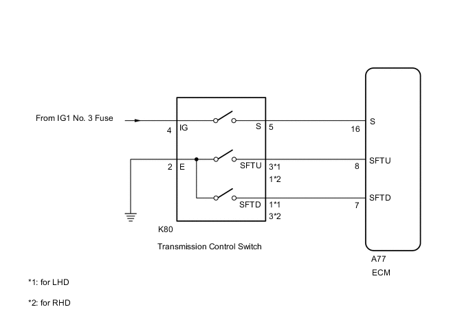
PROCEDURE
-
INSPECT TRANSMISSION CONTROL SWITCH (TRANSMISSION FLOOR SHIFT ASSEMBLY)
-
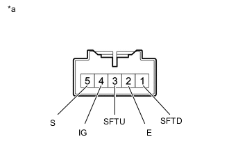
*a Component without harness connected
(Transmission Control Switch for LHD)
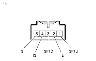
*a Component without harness connected
(Transmission Control Switch for RHD)
Disconnect the transmission control switch connector.
-
Measure resistance between each terminal of transmission control switch when the shift lever is moved to each position.
Standard Resistance (for LHD) Tester Connection Condition Specified Condition 4 - 5 M, "+" and "-" Below 1 Ω Except M, "+" and "-" 10 kΩ or higher 3 - 2 Press continuously "+" (Up shift) Below 1 Ω M 10 kΩ or higher 1 - 2 Press continuously "-" (Down shift) Below 1 Ω M 10 kΩ or higher Standard Resistance (for RHD) Tester Connection Condition Specified Condition 4 - 5 M, "+" and "-" Below 1 Ω Except M, "+" and "-" 10 kΩ or higher 1 - 2 Press continuously "+" (Up shift) Below 1 Ω M 10 kΩ or higher 3 - 2 Press continuously "-" (Down shift) Below 1 Ω M 10 kΩ or higher Result Proceed to OK NG
NG 
REPLACE TRANSMISSION CONTROL SWITCH (TRANSMISSION FLOOR SHIFT ASSEMBLY) Click here
OK 
-
-
CHECK HARNESS AND CONNECTOR (TRANSMISSION CONTROL SWITCH - BATTERY, BODY GROUND)
-
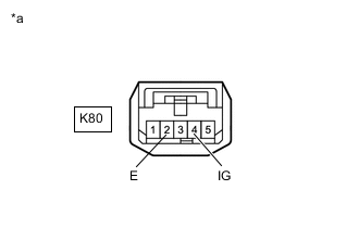
*a Front view of wire harness connector
(to Transmission Control Switch)
Measure the voltage according to the value(s) in the table below.
Standard Voltage Tester Connection Condition Specified Condition K80-4 (IG) - Body ground Engine switch on (IG) 11 to 14 V Engine switch off Below 1 V -
Turn the engine switch off position.
-
Measure the resistance according to the value(s) in the table below.
Standard Resistance Tester Connection Condition Specified Condition K80-2 (E) - Body ground Always Below 1 Ω Result Proceed to OK NG
NG
REPAIR OR REPLACE HARNESS OR CONNECTOR
OK
-
-
CHECK HARNESS AND CONNECTOR (TRANSMISSION CONTROL SWITCH - ECM)
-
Connect the transmission control switch connector.
-
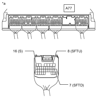
*a Rear view of wire harness connector
(to ECM)
Disconnect the A77 ECM connector.
-
Turn the engine switch on (IG), and measure the voltage according to the value(s) in the table below when the shift lever is moved to each position.
Standard Voltage Tester Connection Shift Position Specified Condition A77-16 (S) - Body ground M, "+" and "-" 11 to 14 V Except M, "+" and "-" Below 1 V -
Turn the engine switch off.
-
Measure the resistance according to the value(s) in the table below when the shift lever is moved to each position.
Standard Resistance Tester Connection Shift Position Specified Condition A77-8 (SFTU) - Body ground Press continuously "+" (Up shift) Below 1 Ω M 10 kΩ or higher A77-7 (SFTD) - Body ground Press continuously "-" (Down shift) Below 1 Ω M 10 kΩ or higher Result Proceed to OK NG
OK
PROCEED TO NEXT SUSPECTED AREA SHOWN IN PROBLEM SYMPTOMS TABLE Click here
NG
REPAIR OR REPLACE HARNESS OR CONNECTOR
-