STOP AND START SYSTEM Starter Signal Circuit
DESCRIPTION
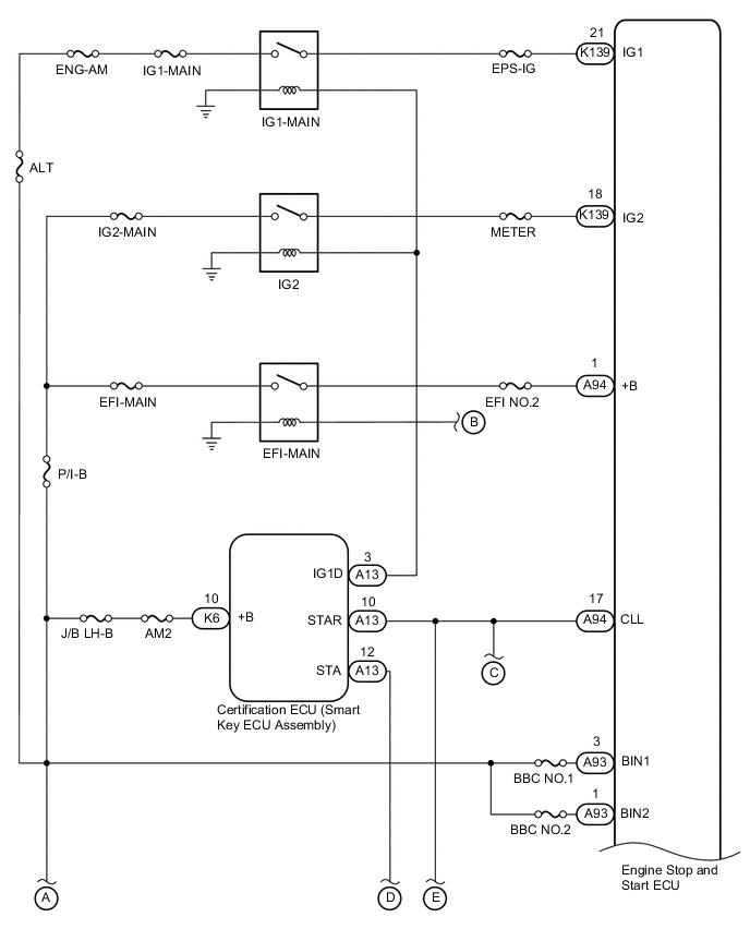
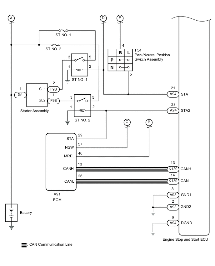
By using the starter delay circuit, the engine stop and start ECU can activate the ST NO. 2 relay (for starter motor operation) after activating the ST NO. 1 relay (for starter pinion operation) to operate the starter assembly.
WIRING DIAGRAM
CAUTION / NOTICE / HINT
Note
-
Before replacing the engine stop and start ECU, read the number of starter operations and total number of engine starts and write it into a new engine stop and start ECU.
-
After replacing the engine stop and start ECU or air conditioning amplifier assembly, reset and perform learning of the air conditioning information in the engine stop and start ECU.
-
After replacing the engine stop and start ECU or yaw rate sensor, clear and calibrate the deceleration sensor zero point in the engine stop and start ECU.
-
When the engine stop and start ECU is replaced, check the oil pump assembly with solenoid.
-
After replacing the starter assembly, perform initialization of the number of starter operations stored in the engine stop and start ECU.
-
When the starter assembly is replaced, "ST NO. 1 relay" and "ST NO. 2 relay" must be also replaced.
-
Inspect the fuses for circuits related to this system before performing the following procedure.
PROCEDURE
-
CHECK CRANKING
-
Turn the engine switch on (START) and check that the engine cranks.
Result Result Proceed to Engine cranks A Engine does not crank B
B 
PERFORM ACTIVE TEST USING GTS (STARTER) Click here
A 
-
-
PERFORM ACTIVE TEST USING GTS (STARTER)
-
Connect the GTS to the DLC3.
-
Turn the engine switch on (IG).
-
Turn the GTS on.
-
Enter the following menus: Powertrain / Stop and Start / Active Test / Starter.
Powertrain > Stop and Start > Active TestTester Display Starter -
Check whether the engine cranks while the Active Test "Starter" is being performed.
Note
The Active Test "Starter" is stopped automatically 3 seconds after the starter assembly begins operating.
Standard Engine cranks Result Proceed to OK NG
OK 
GO TO DTC P1603 (CONFIRM CAUSE OF ENGINE STALL) Click here
NG
-
-
CHECK HARNESS AND CONNECTOR (ENGINE STOP AND START ECU POWER SOURCE CIRCUIT)
-
Disconnect the A93, A94 and K139 engine stop and start ECU connectors.
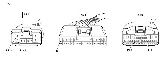
*a Front view of wire harness connector
(to Engine Stop and Start ECU)
- - -
Measure the voltage according to the value(s) in the table below.
Standard Voltage Tester Connection Condition Specified Condition A93-1 (BIN2) - Body ground Always 9.5 to 14 V A93-3 (BIN1) - Body ground Always 9.5 to 14 V -
Turn the engine switch on (IG).
-
Measure the voltage according to the value(s) in the table below.
Standard Voltage Tester Connection Condition Specified Condition A94-1 (+B) - Body ground Engine switch on (IG) 9.5 to 14 V K139-18 (IG2) - Body ground Engine switch on (IG) 9.5 to 14 V K139-21 (IG1) - Body ground Engine switch on (IG) 9.5 to 14 V Result Proceed to OK NG
NG
REPAIR OR REPLACE HARNESS OR CONNECTOR
OK
-
-
CHECK HARNESS AND CONNECTOR (ENGINE STOP AND START ECU - BODY GROUND)
-
Disconnect the A93 and A94 engine stop and start ECU connectors.
-
Measure the resistance according to the value(s) in the table below.
Standard Resistance Tester Connection Condition Specified Condition A93-2 (GND2) - Body ground Always Below 1 Ω A93-8 (GND1) - Body ground Always Below 1 Ω A94-6 (DGND) - Body ground Always Below 1 Ω Result Proceed to OK NG
OK
REPLACE ENGINE STOP AND START ECU Click here
NG
REPAIR OR REPLACE HARNESS OR CONNECTOR
-
-
PERFORM ACTIVE TEST USING GTS (STARTER)
-
Connect the GTS to the DLC3.
-
Turn the engine switch on (IG).
-
Turn the GTS on.
-
Enter the following menus: Powertrain / Stop and Start / Active Test / Starter.
Powertrain > Stop and Start > Active TestTester Display Starter -
Check whether the engine cranks while the Active Test "Starter" is being performed.
Note
The Active Test "Starter" is stopped automatically 3 seconds after the starter assembly begins operating.
Standard Engine cranks Result Result Proceed to Engine cranks A Engine does not crank B
B
CHECK ENGINE STOP AND START ECU (STA, STA2 SIGNAL) Click here
A
-
-
READ VALUE USING GTS (NEUTRAL SWITCH)
-
Connect the GTS to the DLC3.
-
Turn the engine switch on (IG).
-
Turn the GTS on.
-
Enter the following menus: Powertrain / Stop and Start / Data List / Neutral Switch.
-
In accordance with the display on the GTS, read the Data List.
Powertrain > Stop and Start > Data ListTester Display Measurement Item Range Normal Condition Diagnostic Note Neutral Switch Park/neutral position assembly status ON / OFF ON: Shift lever in P or N
OFF: Shift lever not in P or N
-
Powertrain > Stop and Start > Data ListTester Display Neutral Switch OK Tester Display Condition Normal Condition Neutral Switch Shift lever in P or N ON Shift lever not in P or N OFF Result Proceed to OK NG
NG
CHECK HARNESS AND CONNECTOR (CERTIFICATION ECU (SMART KEY ECU ASSEMBLY) - ENGINE STOP AND START ECU) Click here
OK
-
-
INSPECT PARK/NEUTRAL POSITION SWITCH ASSEMBLY
-
Inspect the park/neutral position switch assembly.
Result Proceed to OK NG
NG
REPLACE PARK/NEUTRAL POSITION SWITCH ASSEMBLY Click here
OK
-
-
CHECK HARNESS AND CONNECTOR (CERTIFICATION ECU (SMART KEY ECU ASSEMBLY) - ST NO. 1 RELAY)
-
Disconnect the A13 certification ECU (smart key ECU assembly) connector.
-
Remove the ST NO. 1 relay from the No. 2 engine room relay block and No. 2 junction block assembly.
-
Measure the resistance according to the value(s) in the table below.
Standard Resistance Tester Connection Condition Specified Condition A13-10 (STAR) - ST NO. 1 relay terminal 2 Shift lever in P or N Below 1 Ω A13-10 (STAR) - ST NO. 1 relay terminal 2 Shift lever not in P or N 10 kΩ or higher Result Proceed to OK NG
OK
PROCEED TO NEXT SUSPECTED AREA SHOWN IN PROBLEM SYMPTOMS TABLE Click here
NG
REPAIR OR REPLACE HARNESS OR CONNECTOR
-
-
CHECK HARNESS AND CONNECTOR (CERTIFICATION ECU (SMART KEY ECU ASSEMBLY) - ENGINE STOP AND START ECU)
-
Disconnect the F54 park/neutral position switch assembly connector.
-
Disconnect the A13 certification ECU (smart key ECU assembly) connector.
-
Disconnect the A94 engine stop and start ECU connector.
-
Disconnect the A96 ECM connector.
-
Measure the resistance according to the value(s) in the table below.
Standard Resistance Tester Connection Condition Specified Condition A13-10 (STAR) - A94-17 (CLL) Always Below 1 Ω A13-10 (STAR) - Body ground Always 10 kΩ or higher A94-17 (CLL) - Body ground Always 10 kΩ or higher Result Proceed to OK NG
NG
REPAIR OR REPLACE HARNESS OR CONNECTOR
OK
-
-
CHECK CERTIFICATION ECU (SMART KEY ECU ASSEMBLY) (STAR SIGNAL)
-
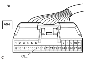
*a Front view of wire harness connector
(to Engine Stop and Start ECU)
Disconnect the engine stop and start ECU connector.
-
Measure the voltage according to the value(s) in the table below.
Standard Voltage Tester Connection Condition Specified Condition A94-17 (CLL) - Body ground Engine started using engine switch (engine switch turned on (START)) 9.5 to 14 V Result Proceed to OK NG
OK
PROCEED TO NEXT SUSPECTED AREA SHOWN IN PROBLEM SYMPTOMS TABLE Click here
NG
GO TO SMART ENTRY AND START SYSTEM Click here
-
-
CHECK ENGINE STOP AND START ECU (STA, STA2 SIGNAL)
-
Connect an oscilloscope to the A94-21 (STA), A94-23 (STA2) and A94-6 (DGND) terminals of the engine stop and start ECU connector.
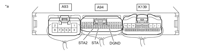
*a Component with harness connected
(Engine Stop and Start ECU)
- - -
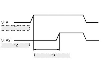
*1 (ST NO. 1 Relay) *2 (ST NO. 2 Relay) *3 0.03 to 0.06 seconds Check the waveform immediately after turning the engine switch on (START).
Item Condition Tester Connection A94-21 (STA) - A94-6 (DGND)
A94-23 (STA2) - A94-6 (DGND)
Condition Engine started by engine switch operation Result Result Proceed to Delay between ST NO. 1 relay turning on and ST NO. 2 relay turning on: between 0.03 and 0.06 seconds A Delay between ST NO. 1 relay turning on and ST NO. 2 relay turning on: not between 0.03 and 0.06 seconds B ST NO. 1 relay turns on and ST NO. 2 relay does not turn on C ST NO. 1 relay and ST NO. 2 relay do not turn on D Note
After replacing the engine stop and start ECU, make sure that the drive plate and ring gear sub-assembly and starter pinion gear are not excessively worn. A malfunction in the delay circuit may cause the drive plate and ring gear sub-assembly or starter pinion gear to be worn or damaged.
B
REPLACE ENGINE STOP AND START ECU Click here
C
CHECK HARNESS AND CONNECTOR (ENGINE STOP AND START ECU POWER SOURCE CIRCUIT) Click here
D
GO TO STEP 15 Click here
A
-
-
INSPECT RELAY (ST NO. 1, ST NO. 2 RELAY)
-
Inspect the ST NO. 1 relay.
-
Inspect the ST NO. 2 relay.
Result Proceed to OK NG
NG
REPLACE RELAY (ST NO. 1, ST NO. 2 RELAY)
OK
-
-
CHECK HARNESS AND CONNECTOR (ST NO. 1, ST NO. 2 RELAY - BATTERY)
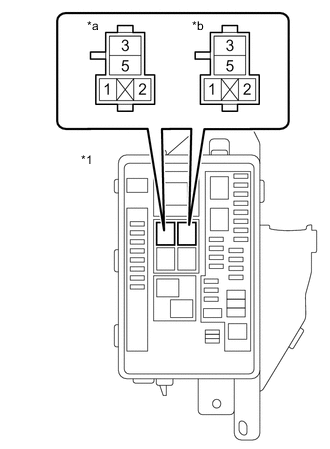
*1 No. 2 Engine Room Relay Block and No. 2 Junction Block Assembly *a ST NO. 1 Relay Terminal *b ST NO. 2 Relay Terminal
-
Remove the ST NO. 1 relay from the No. 2 engine room relay block and No. 2 junction block assembly.
-
Remove the ST NO. 2 relay from the No. 2 engine room relay block and No. 2 junction block assembly.
-
Measure the voltage according to the value(s) in the table below.
Standard Voltage Tester Connection Condition Specified Condition ST NO. 1 relay terminal 5 - Body ground Always 9.5 to 14 V ST NO. 2 relay terminal 5 - Body ground Always 9.5 to 14 V Result Proceed to OK NG
NG
REPAIR OR REPLACE HARNESS OR CONNECTOR
OK
-
-
CHECK HARNESS AND CONNECTOR (ST NO. 1, ST NO. 2 RELAY - STARTER ASSEMBLY)
-
Remove the ST NO. 1 relay from the No. 2 engine room relay block and No. 2 junction block assembly.
-
Remove the ST NO. 2 relay from the No. 2 engine room relay block and No. 2 junction block assembly.
-
Disconnect the F98 starter assembly connector.
-
Measure the resistance according to the value(s) in the table below.
Standard Resistance Tester Connection Condition Specified Condition ST NO. 1 relay terminal 3 - F98-2 (SL1) Always Below 1 Ω ST NO. 2 relay terminal 3 - F98-1 (SL2) Always Below 1 Ω Result Proceed to OK NG
NG
REPAIR OR REPLACE HARNESS OR CONNECTOR
OK
-
-
CHECK HARNESS AND CONNECTOR (ST NO. 1 RELAY - BODY GROUND)
-
Remove the ST NO. 1 relay from the No. 2 engine room relay block and No. 2 junction block assembly.
-
Measure the resistance according to the value(s) in the table below.
Standard Resistance Tester Connection Condition Specified Condition ST NO. 1 relay terminal 1 - Body ground Always Below 1 Ω Result Proceed to OK NG
NG
REPAIR OR REPLACE HARNESS OR CONNECTOR
OK
-
-
CHECK HARNESS AND CONNECTOR (ST NO. 2 RELAY - BODY GROUND)
-
Remove the ST NO. 2 relay from the No. 2 engine room relay block and No. 2 junction block assembly.
-
Measure the resistance according to the value(s) in the table below.
Standard Resistance Tester Connection Condition Specified Condition ST NO. 2 relay terminal 1 - Body ground Always Below 1 Ω Result Proceed to OK NG
NG
REPAIR OR REPLACE HARNESS OR CONNECTOR
OK
-
-
CHECK HARNESS AND CONNECTOR (ENGINE STOP AND START ECU - ST NO. 1 RELAY)
-
Disconnect the A13 certification ECU (smart key ECU assembly) connector.
-
Disconnect the F54 park/neutral position switch assembly connector.
-
Disconnect the A94 engine stop and start ECU connector.
-
Remove the ST NO. 1 relay from the No. 2 engine room relay block and No. 2 junction block assembly.
-
Measure the resistance according to the value(s) in the table below.
Standard Resistance Tester Connection Condition Specified Condition A94-21 (STA) - ST NO. 1 relay terminal 2 Always Below 1 Ω A94-21 (STA) - Body ground Always 10 kΩ or higher ST NO. 1 relay terminal 2 - Body ground Always 10 kΩ or higher Result Proceed to OK NG
NG
REPAIR OR REPLACE HARNESS OR CONNECTOR
OK
-
-
CHECK HARNESS AND CONNECTOR (ENGINE STOP AND START ECU - ST NO. 2 RELAY)
-
Disconnect the A91 ECM connector.
-
Disconnect the A94 engine stop and start ECU connector.
-
Remove the ST NO. 2 relay from the No. 2 engine room relay block and No. 2 junction block assembly.
-
Measure the resistance according to the value(s) in the table below.
Standard Resistance Tester Connection Condition Specified Condition A94-23 (STA2) - ST NO. 2 relay terminal 2 Always Below 1 Ω A94-23 (STA2) - Body ground Always 10 kΩ or higher ST NO. 2 relay terminal 2 - Body ground Always 10 kΩ or higher Result Proceed to OK NG
NG
REPAIR OR REPLACE HARNESS OR CONNECTOR
OK
-
-
CHECK STARTER SIGNAL (OUTPUT WAVEFORM)
-
Enter the following menus: Powertrain / Stop and Start / Active Test / Starter Motor Drive Magnet Switch.
-
Connect the positive (+) lead of an oscilloscope to the positive (+) battery terminal and the negative (-) lead to the negative (-) battery terminal.
-
While performing the Active Test "Starter Motor Drive Magnet Switch" to forcibly operate the starter motor, count the number of times the waveform drops.
Note
-
The Active Test "Starter Motor Drive Magnet Switch" is stopped automatically after the starter motor operates for 3 seconds.
-
Do not forcibly operate the starter pinion.
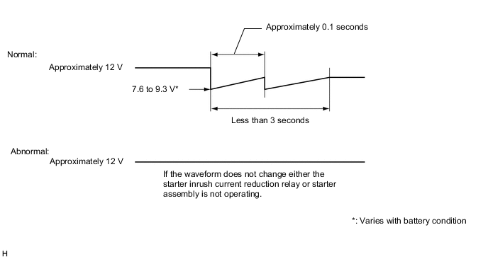
Standard Waveform drops 2 times Result Number of Times Waveform Dropped Proceed to 0 times A 2 times B -
B
INSPECT STARTER ASSEMBLY Click here
A
-
-
INSPECT STARTER INRUSH CURRENT REDUCTION RELAY
-
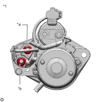
*1 Starter Assembly *a B Terminal *b M Terminal Disconnect the cable from the negative (-) battery terminal.
-
Disconnect terminals B and M of the starter inrush current reduction relay.
-
Measure the resistance according to the value(s) in the table below.
Standard Resistance Tester Connection Condition Specified Condition B Terminal - M Terminal Always Below 1 Ω Result Proceed to OK NG
NG
INSPECT STARTER ASSEMBLY (M TERMINAL) Click here
OK
-
-
INSPECT STARTER ASSEMBLY (C TERMINAL)
-
Disconnect the cable from the negative (-) battery terminal.
-
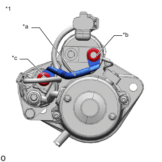
*1 Starter Assembly *a Inspect Part *b C Terminal *c B Terminal Disconnect terminal B of the starter inrush current reduction relay.
-
Disconnect terminal C of the starter assembly.
-
Measure the resistance according to the value(s) in the table below.
Standard Resistance Tester Connection Condition Specified Condition C Terminal - B Terminal Always Below 1 Ω Result Proceed to OK NG
OK
REPLACE STARTER ASSEMBLY Click here
NG
REPAIR OR REPLACE HARNESS OR CONNECTOR
-
-
INSPECT STARTER ASSEMBLY (M TERMINAL)
-
Disconnect the cable from the negative (-) battery terminal.
-
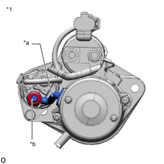
*1 Starter Assembly *a Inspect Part *b M Terminal Disconnect terminal M of the starter inrush current reduction relay.
-
Measure the resistance according to the value(s) in the table below.
Standard Resistance Tester Connection Condition Specified Condition M Terminal - Body ground Always Below 1 Ω Result Proceed to OK NG
OK
REPLACE STARTER INRUSH CURRENT REDUCTION RELAY Click here
NG
REPLACE STARTER ASSEMBLY Click here
-
-
INSPECT STARTER ASSEMBLY
-
Inspect the starter assembly.
Result Proceed to OK NG
OK
PROCEED TO NEXT SUSPECTED AREA SHOWN IN PROBLEM SYMPTOMS TABLE Click here
NG
REPLACE STARTER ASSEMBLY Click here
-
-
CHECK HARNESS AND CONNECTOR (ENGINE STOP AND START ECU POWER SOURCE CIRCUIT)
-
Disconnect the A93, A94 and K139 engine stop and start ECU connectors.
*a Front view of wire harness connector
(to Engine Stop and Start ECU)
- - -
Measure the voltage according to the value(s) in the table below.
Standard Voltage Tester Connection Condition Specified Condition A93-1 (BIN2) - Body ground Always 9.5 to 14 V A93-3 (BIN1) - Body ground Always 9.5 to 14 V -
Turn the engine switch on (IG).
-
Measure the voltage according to the value(s) in the table below.
Standard Voltage Tester Connection Condition Specified Condition A94-1 (+B) - Body ground Engine switch on (IG) 9.5 to 14 V K139-18 (IG2) - Body ground Engine switch on (IG) 9.5 to 14 V K139-21 (IG1) - Body ground Engine switch on (IG) 9.5 to 14 V Result Proceed to OK NG
NG
REPAIR OR REPLACE HARNESS OR CONNECTOR
OK
-
-
CHECK HARNESS AND CONNECTOR (ENGINE STOP AND START ECU - BODY GROUND)
-
Disconnect the A93 and A94 engine stop and start ECU connectors.
-
Measure the resistance according to the value(s) in the table below.
Standard Resistance Tester Connection Condition Specified Condition A93-2 (GND2) - Body ground Always Below 1 Ω A93-8 (GND1) - Body ground Always Below 1 Ω A94-6 (DGND) - Body ground Always Below 1 Ω Result Proceed to OK NG
OK
REPLACE ENGINE STOP AND START ECU Click here
NG
REPAIR OR REPLACE HARNESS OR CONNECTOR
-