DYNAMIC RADAR CRUISE CONTROL SYSTEM, Diagnostic DTC:C1A05
| DTC Code | DTC Name |
|---|---|
| C1A05 | Stop Light Switch Circuit |
DESCRIPTION
When the brake pedal is depressed, the stop light switch assembly sends a brake pedal operation signal to the driving support ECU assembly. After reception of this signal, the driving support ECU cancels the dynamic radar cruise control system. When the driving support ECU assembly detects a problem in the stop light switch assembly circuit, DTC C1A05 is stored.
| DTC No. | Detection Item | DTC Detection Condition | Trouble Area |
|---|---|---|---|
| C1A05 | Stop Light Switch Circuit | When the engine switch is on (IG) and the dynamic radar cruise control system is turned on using the cruise control main switch (ON/OFF button), the driving support ECU assembly detects a malfunction in the signal from the stop light switch assembly circuit. |
|
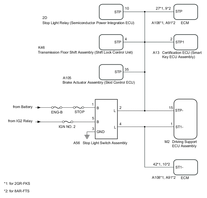
WIRING DIAGRAM
CAUTION / NOTICE / HINT
Note
-
Inspect the fuses for circuits related to this system before performing the following procedure.
-
When replacing the driving support ECU assembly, make sure to replace it with a new one. If a device which was installed to another vehicle is used, the information stored in the driving support ECU assembly will not match the information from the vehicle, and as a result, a DTC may be stored.
PROCEDURE
-
CHECK TERMINAL VOLTAGE (POWER SOURCE OF STOP LIGHT SWITCH ASSEMBLY)
-
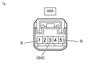
*a Front view of wire harness connector
(to Stop Light Switch Assembly)
Disconnect the A56 stop light switch assembly connector.
-
Measure the voltage and resistance according to the value(s) in the table below.
Standard Voltage Tester Connection Condition Specified Condition A56-1 (B) - Body ground Always 11 to 14 V A56-5 (B) - Body ground Engine switch on (IG) 11 to 14 V Standard Resistance Tester Connection Condition Specified Condition A56-3 (GND) - Body ground Always Below 1 Ω Result Proceed to OK NG
NG 
REPAIR OR REPLACE HARNESS OR CONNECTOR
OK 
-
-
CHECK HARNESS AND CONNECTOR (DRIVING SUPPORT ECU ASSEMBLY - STOP LIGHT SWITCH ASSEMBLY)
-
Disconnect the M2 driving support ECU assembly connector.
-
Disconnect the A56 stop light switch assembly connector.
-
Disconnect the A13 certification ECU (smart key ECU assembly) connector.
-
Disconnect the A105 brake actuator assembly (skid control ECU) connector.
-
Disconnect the K46 transmission floor shift assembly (shift lock control unit) connector.
-
Disconnect the 2D stop light relay (semiconductor power integration ECU) connector.
-
for 2GR-FKS:
-
Disconnect the A108 ECM connector.
-
-
for 8AR-FTS:
-
Disconnect the A91 ECM connector.
-
-
Measure the resistance according to the value(s) in the table below.
Standard Resistance Tester Connection Condition Specified Condition M2-15 (STP-) - A56-2 (L) Always Below 1 Ω M2-1 (ST1-) - A56-4 (L) Always Below 1 Ω M2-15 (STP-) or A56-2 (L) - Body ground Always 10 kΩ or higher M2-1 (ST1-) or A56-4 (L) - Body ground Always 10 kΩ or higher Result Proceed to OK NG
NG
REPAIR OR REPLACE HARNESS OR CONNECTOR
OK
-
-
REPLACE STOP LIGHT SWITCH ASSEMBLY
-
Replace the stop light switch assembly.
Result Proceed to NEXT
NEXT
-
-
CHECK FOR DTCs (RADAR CRUISE)
-
Clear the DTCs.
Powertrain > Radar Cruise > Clear DTCs -
Check for DTCs.
Powertrain > Radar Cruise > Trouble CodesResult Result Proceed to DTC C1A05 is not output A DTC C1A05 is output B
A
END (STOP LIGHT SWITCH ASSEMBLY WAS DEFECTIVE)
B
REPLACE DRIVING SUPPORT ECU ASSEMBLY Click here
-