DYNAMIC RADAR CRUISE CONTROL SYSTEM, Diagnostic DTC:C1A4B
| DTC Code | DTC Name |
|---|---|
| C1A4B | Stop Light Relay Circuit |
DESCRIPTION
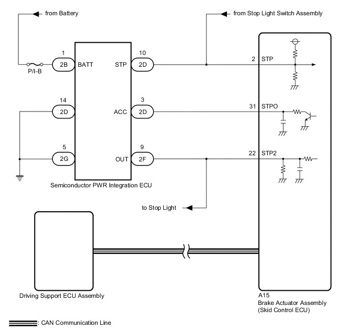
The brake actuator assembly (skid control ECU) sends a stop light operation signal to the semiconductor PWR integration ECU. When the brake actuator assembly (skid control ECU) detects a malfunction in the stop light circuit, the driving support ECU assembly stores DTC C1A4B.
| DTC No. | Detection Item | DTC Detection Condition | Trouble Area |
|---|---|---|---|
| C1A4B | Stop Light Relay Circuit | Either of the following conditions is met:
|
|
WIRING DIAGRAM
CAUTION / NOTICE / HINT
Note
-
Inspect the fuses for circuits related to this system before performing the following procedure.
-
When this DTC is output, a malfunction in the lighting system is suspected. Check if the lighting system is functioning normally.
PROCEDURE
-
INSPECT ENGINE START
-
Depress the brake pedal, push the engine switch and check that the engine starts.
OK The engine starts. Result Proceed to OK NG
NG 
GO TO SFI SYSTEM for 2GR-FSE: Click here
GO TO SFI SYSTEM for 4GR-FSE (w/ Canister Pump Module): Click here
GO TO SFI SYSTEM for 4GR-FSE (w/o Canister Pump Module): Click hereOK 
-
-
CHECK STOP LIGHT OPERATION
-
Check that the stop lights come on when the brake pedal is depressed and go off when the brake pedal is released.
OK The stop lights illuminate when the brake pedal is depressed. The stop lights turn off when the brake pedal is released. Result Proceed to OK NG
NG
GO TO LIGHTING SYSTEM Click here
OK
-
-
INSPECT SEMICONDUCTOR PWR INTEGRATION ECU
-
Using a voltmeter, check the signal reading of the semiconductor PWR integration ECU.
OK Output signal reading is normal. Result Proceed to OK NG
NG
INSPECT SEMICONDUCTOR PWR INTEGRATION ECU (RESULTS OF SIGNAL READING CHECK) Click here
OK
-
-
CHECK HARNESS AND CONNECTOR (STPO TERMINAL VOLTAGE)
-
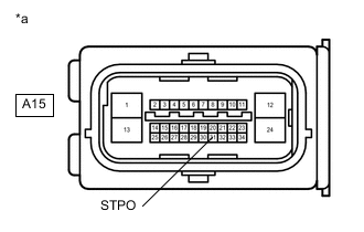
*a Front view of wire harness connector
(to Brake Actuator Assembly (Skid Control ECU))
Turn the engine switch off.
-
Disconnect the A15 brake actuator assembly (skid control ECU) connector.
-
Measure the voltage according to the value(s) in the table below.
Standard Voltage Tester Connection Condition Specified Condition A15-31 (STPO) - Body ground Always 11 to 14 V -
Connect the A15 brake actuator assembly (skid control ECU) connector.
Result Proceed to OK NG
NG 
CHECK HARNESS AND CONNECTOR (BRAKE ACTUATOR ASSEMBLY (SKID CONTROL ECU) - SEMICONDUCTOR PWR INTEGRATION ECU) Click here
OK
-
-
PERFORM ACTIVE TEST USING GTS (STOP LIGHT RELAY)
-
According to the display on the GTS, perform the Active Test Stop Light Relay.
Chassis > ABS/VSC/TRC > Active TestTester Display Measurement Item Control Range Diagnostic Note Stop Light Relay Stop light control relay (STOP LP) ON or OFF Stop lights come on
Chassis > ABS/VSC/TRC > Active TestActive Test Display Stop Light Relay Data List Display Stop Light Relay Output -
According to the display on the GTS, read the Data List item Stop Light Relay Output.
Chassis > ABS/VSC/TRC > Data ListTester Display Measurement Item Range Normal Condition Diagnostic Note Stop Light Relay Output Stop light control relay (STOP LP) output ON or OFF ON: Relay output on (Stop light on)
OFF: Relay output off (Stop light off)
- -
Check that the Data List item Stop Light Relay Output changes between ON and OFF and the stop lights turn on and off according to the operation of the Active Test.
Result Result Proceed to The Data List item Stop Light Relay Output does not change between ON and OFF and the stop lights do not turn ON and OFF according to the operation of the Active Test. A The Data List item Stop Light Relay Output changes between ON and OFF but the stop lights do not turn ON and OFF according to the operation of the Active Test. B
B
CHECK HARNESS AND CONNECTOR (BRAKE ACTUATOR ASSEMBLY (SKID CONTROL ECU) - SEMICONDUCTOR PWR INTEGRATION ECU) Click here
A
-
-
INSPECT BRAKE ACTUATOR ASSEMBLY (SKID CONTROL ECU)
-
According to the display on the GTS, perform the Active Test Stop Light Relay.
Chassis > ABS/VSC/TRC > Active TestTester Display Measurement Item Control Range Diagnostic Note Stop Light Relay Stop light control relay (STOP LP) ON or OFF Stop lights come on
Chassis > ABS/VSC/TRC > Active TestTester Display Stop Light Relay -
Measure the voltage according to the value(s) in the table below.
Tech Tips
Do not disconnect the semiconductor PWR integration ECU connector.
Standard Voltage Tester Connection Condition Specified Condition 2D-3 (ACC) - Body ground Engine switch on (IG)
(Active test OFF)
11 to 14 V 2D-3 (ACC) - Body ground Engine switch on (IG)
(Active test ON)
Below 1.5 V Result Proceed to OK NG
OK
REPLACE SEMICONDUCTOR PWR INTEGRATION ECU Click here
NG
REPLACE BRAKE ACTUATOR ASSEMBLY (SKID CONTROL ECU) for LHD: Click here
REPLACE BRAKE ACTUATOR ASSEMBLY (SKID CONTROL ECU) for RHD: Click here -
-
CHECK HARNESS AND CONNECTOR (BRAKE ACTUATOR ASSEMBLY (SKID CONTROL ECU) - SEMICONDUCTOR PWR INTEGRATION ECU)
-
Turn the engine switch off.
-
Disconnect the A15 brake actuator assembly (skid control ECU) connector.
-
Disconnect the 2F semiconductor PWR integration ECU connector.
-
Measure the resistance according to the value(s) in the table below.
Standard Resistance Tester Connection Condition Specified Condition A15-22 (STP2) - 2F-9 (OUT) Always Below 1 Ω Result Proceed to OK NG
OK
REPLACE BRAKE ACTUATOR ASSEMBLY (SKID CONTROL ECU) for LHD: Click here
REPLACE BRAKE ACTUATOR ASSEMBLY (SKID CONTROL ECU) for RHD: Click hereNG
REPAIR OR REPLACE HARNESS OR CONNECTOR
-
-
CHECK HARNESS AND CONNECTOR (BRAKE ACTUATOR ASSEMBLY (SKID CONTROL ECU) - SEMICONDUCTOR PWR INTEGRATION ECU)
-
Turn the engine switch off.
-
Disconnect the A15 brake actuator assembly (skid control ECU) connector.
-
Disconnect the 2D semiconductor PWR integration ECU connector.
-
Measure the resistance according to the value(s) in the table below.
Standard Resistance Tester Connection Condition Specified Condition A15-31 (STPO) - 2D-3 (ACC) Always Below 1 Ω A15-31 (STPO) or 2D-3 (ACC) - Body ground Always 10 kΩ or higher Result Proceed to OK NG
OK
REPLACE SEMICONDUCTOR PWR INTEGRATION ECU Click here
NG
REPAIR OR REPLACE HARNESS OR CONNECTOR
-