CRUISE CONTROL SYSTEM(for 8AR-FTS, 2GR-FKS) Cruise Control Switch Circuit
DESCRIPTION
The cruise control main switch is used to turn the cruise control system on and off, as well as operate 7 functions: SET, - (COAST), TAP-DOWN, RES (RESUME), + (ACCEL), TAP-UP and CANCEL. The SET, TAP-DOWN and - (COAST) functions, and the RES (RESUME), TAP-UP and + (ACCEL) functions are operated with the same switch. The cruise control main switch is an automatic return type switch which turns on only while operating it in the direction of each arrow and turns off after releasing it. The internal contact points of the cruise control main switch turn on with switch operation. Then the ECM reads the voltage value that has been changed by the switch operation to control the SET, - (COAST), RES (RESUME), + (ACCEL), and CANCEL functions.
WIRING DIAGRAM
Figure 1. for 8AR-FTS:
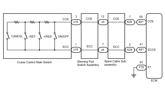
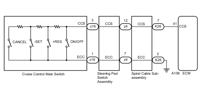
Figure 2. for 2GR-FKS:
CAUTION / NOTICE / HINT
Note
-
The vehicle is equipped with a Supplemental Restraint System (SRS) which includes components such as airbags. Before servicing (including removal or installation of parts), be sure to read the precaution for Supplemental Restraint System.
-
Before replacing the ECM, refer to Service Bulletin.
PROCEDURE
-
READ VALUE ON GTS
-
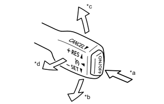
*a ON/OFF *b -/SET *c +/RES *d CANCEL Connect the GTS to the DLC3.
-
Turn the engine switch on (IG).
-
Turn the GTS on.
-
Enter the following menus: Powertrain / Cruise Control / Data List.
-
Check the Data List to confirm proper functioning of the cruise control main switch.
Powertrain > Cruise Control > Data ListTester Display Measurement Item Range Normal Condition Diagnostic Note Cancel Switch CANCEL switch signal ON or OFF ON: CANCEL switch on
OFF: CANCEL switch off
- -SET Switch -SET switch signal ON or OFF ON: -SET switch on
OFF: -SET switch off
- +RES Switch +RES switch signal ON or OFF ON: +RES switch on
OFF: +RES switch off
- Cruise Ready Main-CPU Cruise control system standby condition (Main-CPU) ON or OFF ON: Cruise control switch (ON/OFF switch) pushed
OFF: Cruise control switch (ON/OFF switch) released
- Cruise Ready Sub-CPU Cruise control system standby condition (Sub-CPU) ON or OFF ON: Cruise control main switch (Main-CPU) SET
OFF: Cruise control main switch (Main-CPU) UNSET
-
Powertrain > Cruise Control > Data ListTester Display Cancel Switch -SET Switch +RES Switch Cruise Ready Main-CPU Cruise Ready Sub-CPU OK The Data List items shown in the table change according to the operation of the cruise control main switch. Result Proceed to OK NG
OK 
PROCEED TO NEXT SUSPECTED AREA SHOWN IN PROBLEM SYMPTOMS TABLE Click here
NG 
-
-
INSPECT CRUISE CONTROL MAIN SWITCH
-
Remove the cruise control main switch.
-
Inspect the cruise control main switch.
Result Proceed to OK NG
NG
REPLACE CRUISE CONTROL MAIN SWITCH Click here
OK
-
-
INSPECT STEERING PAD SWITCH ASSEMBLY
-
Remove the steering pad switch assembly.
w/o Pre-collision System: Click here
w/ Pre-collision System: Click here
-
Inspect the steering pad switch assembly.
w/o Pre-collision System: Click here
w/ Pre-collision System: Click here
Result Proceed to OK NG
NG
REPLACE STEERING PAD SWITCH ASSEMBLY w/o Pre-collision System: Click here
REPLACE STEERING PAD SWITCH ASSEMBLY w/ Pre-collision System: Click hereOK
-
-
INSPECT SPIRAL CABLE SUB-ASSEMBLY
-
Remove the spiral cable sub-assembly.
-
Inspect the spiral cable sub-assembly.
Result Proceed to OK NG
NG
REPLACE SPIRAL CABLE SUB-ASSEMBLY Click here
OK
-
-
CHECK HARNESS AND CONNECTOR (SPIRAL CABLE SUB-ASSEMBLY - ECM AND BODY GROUND)
-
Disconnect the K26 spiral cable sub-assembly connector.
-
for 8AR-FTS:
-
Disconnect the A91 ECM connector.
-
-
for 2GR-FKS:
-
Disconnect the A108 ECM connector.
-
-
Measure the resistance according to the value(s) in the table below.
Standard Resistance (for 8AR-FTS) Tester Connection Condition Specified Condition A91-55 (CCS) - K26-7 (CCS) Always Below 1 Ω A91-41 (ECCS) - K26-2 (ECC) Always Below 1 Ω A91-55 (CCS) or K26-7 (CCS) - Body ground Always 10 kΩ or higher A91-41 (ECCS) or K26-2 (ECC) - Body ground Always 10 kΩ or higher Standard Resistance (for 2GR-FKS) Tester Connection Condition Specified Condition A108-41 (CCS) - K26-7 (CCS) Always Below 1 Ω K26-2 (ECC) - Body ground Always Below 1 Ω A108-41 (CCS) or K26-7 (CCS) - Body ground Always 10 kΩ or higher Result Result Proceed to OK (for 8AR-FTS) A OK (for 2GR-FKS) B NG C
B
REPLACE ECM Click here
C
REPAIR OR REPLACE HARNESS OR CONNECTOR
A
-
-
CHECK HARNESS AND CONNECTOR (ECM - BODY GROUND)
-
Disconnect the F78 ECM connector.
-
Measure the resistance according to the value(s) in the table below.
Standard Resistance Tester Connection Condition Specified Condition F78-53 (E1) - Body ground Always Below 1 Ω Result Proceed to OK NG
OK
REPLACE ECM Click here
NG
REPAIR OR REPLACE HARNESS OR CONNECTOR
-