AUTOMATIC TRANSMISSION UNIT(for 2GR) REASSEMBLY

PROCEDURE
-
BEARING POSITION
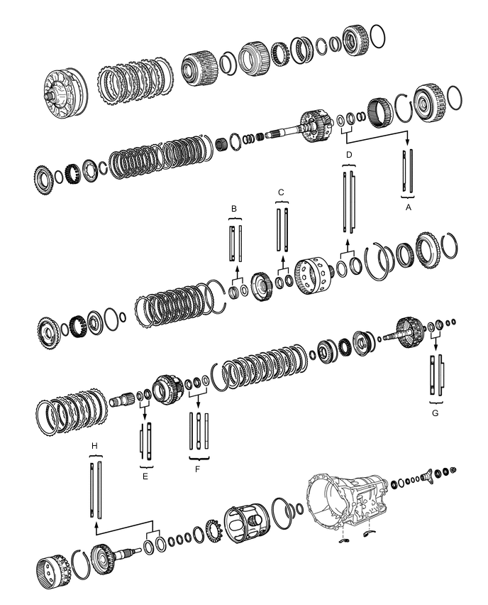
Bearing Position Position Front Race Diameter
Inside/Outside
Thrust Bearing Diameter
Inside/Outside
Rear Race Diameter
Inside/Outside
A - 36.2 mm (1.425 in.) / 58.2 mm (2.291 in.) 44.0 mm (1.732 in.) / 62.0 mm (2.441 in.) B - 34.5 mm (1.358 in.) / 49.4 mm (1.945 in.) 36.6 mm (1.441 in.) / 51.9 mm (2.043 in.) C 46.5 mm (1.831 in.) / 60.1 mm (2.366 in.) 47.0 mm (1.850 in.) / 61.9 mm (2.437 in.) - D - 71.9 mm (2.831 in.) / 85.6 mm (3.370 in.) 72.7 mm (2.858 in.) / 89.2 mm (3.512 in.) E 30.0 mm (1.181 in.) / 49.9 mm (1.965 in.) 31.0 mm (1.221 in.) / 53.1 mm (2.091 in.) - F 31.5 mm (1.240 in.) / 53.0 mm (2.0866 in.) 28.7 mm (1.130 in.) / 52.3 mm (2.059 in.) 28.7 mm (1.130 in.) / 50.4 mm (1.984 in.) G - 30.5 mm (1.201 in.) / 55.7 mm (2.189 in.) 33.5 mm (1.319 in.) / 59.0 mm (2.323 in.) H - 58.9 mm (2.319 in.) / 76.7 mm (3.043 in.) 62.0 mm (2.441 in.) / 82.5 mm (3.248 in.) -
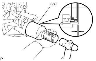
INSTALL OUTPUT SHAFT REAR RADIAL BALL BEARING
-
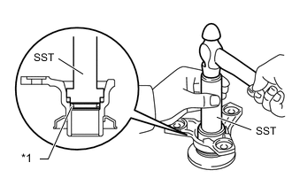
Using SST, tap in the output shaft rear radial ball bearing to the automatic transmission case sub-assembly.
- SST
- 09316-60011 ( 09316-00011, 09316-00021 )
-
Using needle-nose pliers, install the snap ring.
-
-
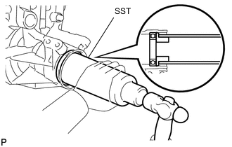
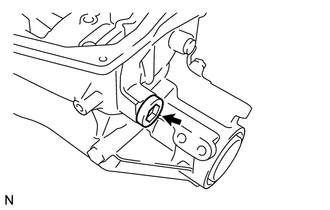
INSTALL AUTOMATIC TRANSMISSION REAR OIL SEAL
-
Coat the lip of a new automatic transmission rear oil seal with MP grease.
-
Using SST and a hammer, tap in the automatic transmission rear oil seal until it fits with the automatic transmission case sub-assembly.
- SST
- 09214-76011
Standard oil seal depth 3.3 to 3.7 mm (0.1300 to 0.1456 in.)
-
-
INSTALL BRAKE PLATE STOPPER SPRING
-
Install the 2 brake plate stopper springs.
-
-
INSTALL NO. 2 BRAKE PISTON
-
Coat 3 new O-rings with ATF, and install them to the No. 2 brake piston.
-
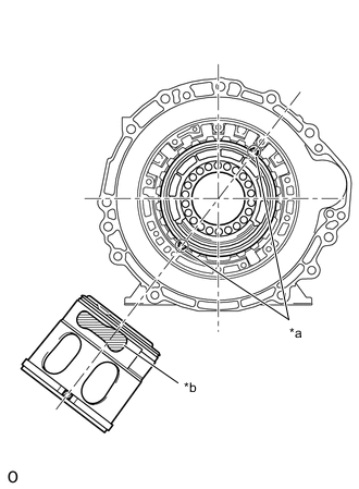
*a Spline *b Parking Hole Install the No. 2 brake piston to the automatic transmission case sub-assembly.
Tech Tips
Make sure that the parking hole of the No. 2 brake piston is on the bottom side by engaging the brake piston's 2 protrusions to the transmission case's spline grooves. (One groove is 3 places clockwise from the top, and the other is 2 places clockwise from the bottom).
-
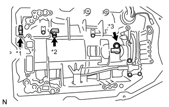
Install the 2nd brake piston return spring sub-assembly to the automatic transmission case sub-assembly.
-
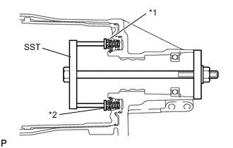
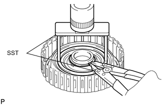
*1 2nd Brake Piston Return Spring Sub-assembly *2 Snap Ring Set SST on the 2nd brake piston return spring sub-assembly, tighten SST and compress the 2nd brake piston return spring sub-assembly.
- SST
- 09380-50010 ( 09381-05010, 09381-05020 )
-
Using SST, install the snap ring.
- SST
- 09350-30020 ( 09350-07070 )
-
-
INSPECT PACK CLEARANCE OF NO. 2 BRAKE
-
INSTALL DIRECT CLUTCH PISTON
-
Coat a new O-ring with ATF, and install it to the direct clutch drum sub-assembly.
-
Coat a new O-ring with ATF, and install it to the direct clutch piston.
-
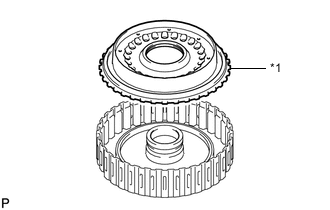
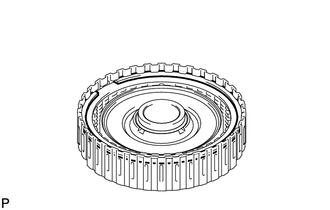
*1 Direct Clutch Piston Install the direct clutch piston to the direct clutch drum sub-assembly.
-
Coat a new O-ring with ATF, and install it to the No. 2 clutch balancer.
-
*1 No. 2 Clutch Balance *2 Direct Clutch Return Spring Sub-assembly Install the direct clutch return spring sub-assembly and No. 2 clutch balancer to the direct clutch drum sub-assembly.
-
Place SST on the No. 2 clutch balancer and compress the direct clutch return spring sub-assembly with a press.
- SST
- 09387-00020
-
Using SST, install the snap ring.
- SST
- 09350-30020 ( 09350-07070 )
-
-
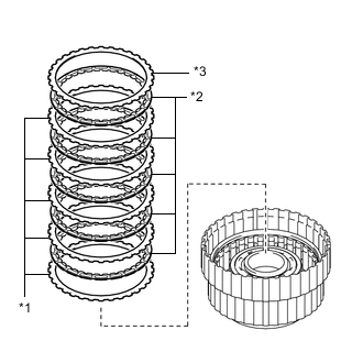
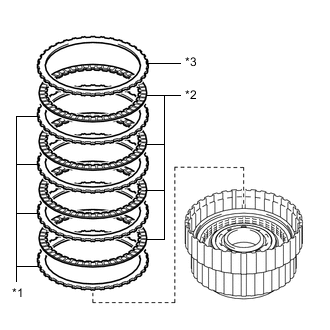
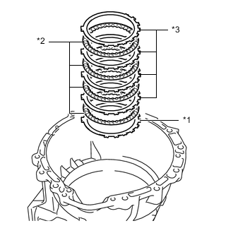
INSTALL NO. 2 CLUTCH DISC
-
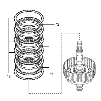
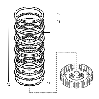
*1 No. 2 Clutch Flange *2 No. 2 Clutch Disc *3 No. 2 Clutch Plate Install the 5 No. 2 clutch plates, 5 No. 2 clutch discs and the No. 2 clutch flange to the direct clutch drum sub-assembly.
Install in order *1 - *2 - *3 - *2 - *3 - *2 - *3 - *2 - *3 - *2 - *3 Note
Make sure that the No. 2 clutch discs, No. 2 clutch plates and the No. 2 clutch flange are installed in the correct order.
-
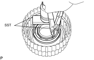
Install the snap ring to the direct clutch drum sub-assembly.
-
-
INSPECT PACK CLEARANCE OF NO. 2 CLUTCH
-
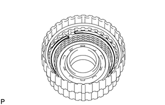
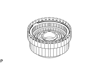
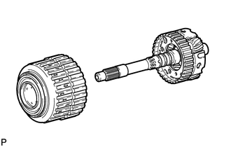
INSTALL MULTIPLE DISC CLUTCH ASSEMBLY
-
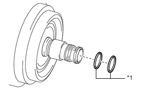
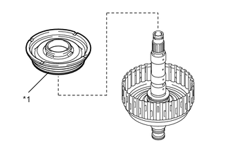
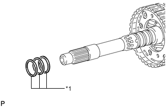
*1 Oil Seal Ring Coat 2 new oil seal rings with ATF, and install them to the multiple disc clutch assembly.
Note
Do not expand the ring ends excessively.
-
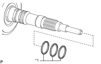
*1 Oil Seal Ring Coat 3 new oil seal rings with ATF, and install them to the output shaft sub-assembly.
Note
Do not expand the ring ends excessively.
-
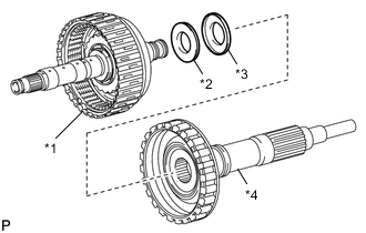
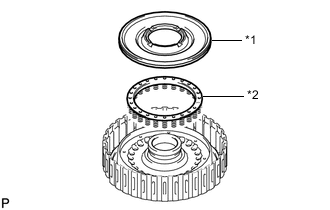
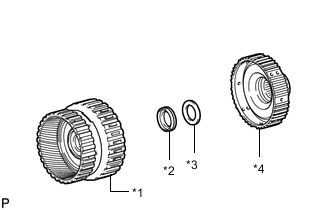
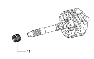
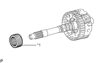
*1 Multiple Disc Clutch Assembly *2 Thrust Needle Roller Bearing *3 Thrust Bearing Race *4 Output Shaft Sub-assembly Install the thrust needle roller bearing and thrust bearing race.
Standard bearing and race diameter Item Inside Outside Thrust needle roller bearing 30.5 mm (1.201 in.) 55.7 mm (2.189 in.) Thrust bearing race 33.5 mm (1.319 in.) 59.0 mm (2.323 in.) Note
Use a small amount of MP grease to make the thrust needle roller bearing and thrust bearing race stay securely in place.
-
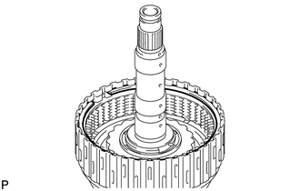
Install the multiple disc clutch assembly to the output shaft sub-assembly.
-
-
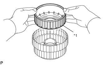
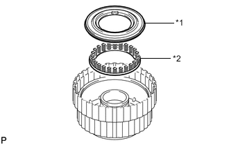
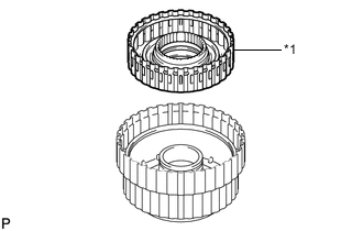
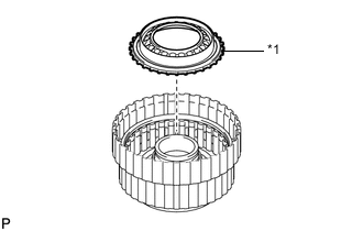
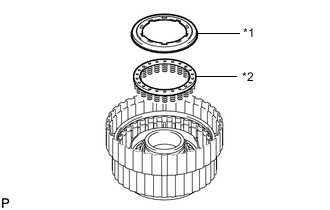
INSTALL REAR PLANETARY RING GEAR
-
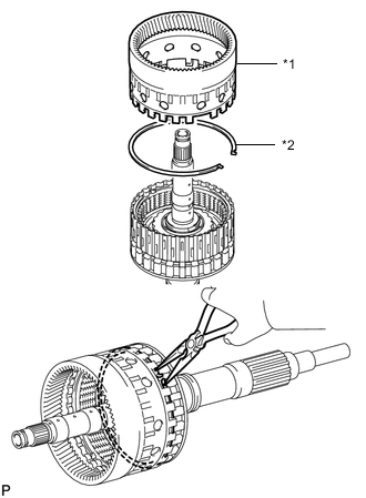
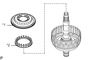
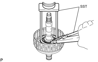
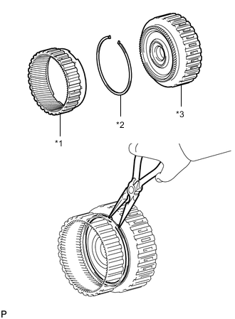
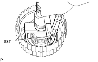
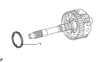
*1 Rear Planetary Ring Gear *2 Snap Ring Install the snap ring to the groove of the output shaft sub-assembly.
-
Using needle-nose pliers, attach the snap ring to install the rear planetary ring gear to the output shaft sub-assembly.
-
-
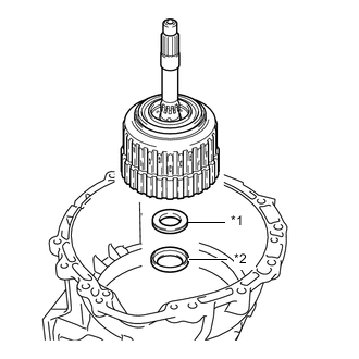
INSTALL MULTIPLE DISC CLUTCH ASSEMBLY WITH REAR PLANETARY RING GEAR AND OUTPUT SHAFT SUB-ASSEMBLY
-
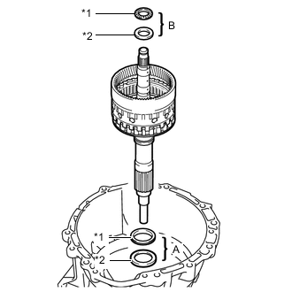
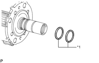
*1 Thrust Needle Roller Bearing *2 Thrust Bearing Race Install the 2 thrust needle roller bearings, 2 thrust bearing races, multiple disc clutch assembly with rear planetary ring gear and output shaft sub-assembly to the automatic transmission case sub-assembly.
Standard bearing and race diameter Item Inside Outside Thrust bearing race A 62.0 mm (2.441 in.) 82.5 mm (3.248 in.) Thrust needle roller bearing A 58.9 mm (2.319 in.) 76.7 mm (3.020 in.) Thrust bearing race B 28.7 mm (1.130 in.) 50.4 mm (1.984 in.) Thrust needle roller bearing B 28.7 mm (1.130 in.) 52.3 mm (2.059 in.) Note
Use a small amount of MP grease to make the thrust needle roller bearing and thrust bearing race stay securely in place.
-
-
INSTALL AUTOMATIC TRANSMISSION FLANGE YOKE ASSEMBLY
-
Coat the lip of a new oil seal with MP grease.
-
*1 Oil Seal Using SST and a hammer, tap in the oil seal.
- SST
- 09517-36010
Oil seal drive in depth 0 to 0.3 mm (0 to 0.0118 in.) -
Install the rear cover sleeve and 2 rear No. 1 output shaft bearing spacers.
-
Install the automatic transmission flange yoke assembly.
-
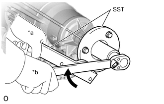
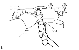
*a Hold *b Turn Set SST.
- SST
- 09330-00021
- 09950-30012 ( 09955-03040 )
-
Using SST and a 30 mm deep socket wrench, temporarily install and tighten a new lock nut.
- Torque:
- 135 N*m { 1377 kgf*cm, 100 ft.*lbf }
-
-
SELECT REAR COVER SLEEVE
-
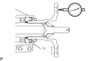
*1 Rear Cover Sleeve Using a dial indicator, measure the output shaft end play. Then choose from the 15 sleeve thicknesses in the table so that the measured value is within the standard value.
Standard end play 0.21 to 0.36 mm (0.0083 to 0.0142 in.) Sleeve thickness Part No. Mark Thickness 35155-50080 02 1.725 to 1.775 (0.0679 to 0.0699 in.) 35155-50090 03 1.775 to 1.825 (0.0699 to 0.0719 in.) 35155-50100 04 1.825 to 1.875 (0.0719 to 0.0738 in.) 35155-50110 05 1.875 to 1.925 (0.0738 to 0.0758 in.) 35155-50120 06 1.925 to 1.975 (0.0758 to 0.0778 in.) 35155-50130 07 1.975 to 2.025 (0.0778 to 0.0797 in.) 35155-50140 08 2.025 to 2.025 (0.0778 to 0.0797 in.) 35155-50150 09 2.075 to 2.125 (0.0817 to 0.0837 in.) 35155-50160 10 2.125 to 2.175 (0.0837 to 0.0856 in.) 35155-50170 11 2.175 to 2.225 (0.0778 to 0.0797 in.) 35155-50180 12 2.225 to 2.275 (0.0876 to 0.0896 in.) 35155-50190 13 2.275 to 2.325 (0.0896 to 0.0915 in.) 35155-50200 14 2.325 to 2.375 (0.0915 to 0.0935 in.) 35155-50210 15 2.375 to 2.425 (0.0935 to 0.0955 in.) 35155-50220 16 2.425 to 2.475 (0.0955 to 0.0974 in.) -
Temporarily remove the lock nut, automatic transmission flange yoke assembly, 2 rear No. 1 output shaft bearing spacers and rear cover sleeve, attach the automatic transmission flange yoke assembly.
-
Using a chisel and hammer, securely stake the lock nut.
-
-
INSTALL REAR PLANETARY GEAR ASSEMBLY
-
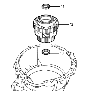
*1 Thrust Needle Roller Bearing *2 Rear Planetary Gear Assembly *3 Thrust Bearing Race Install the thrust bearing race, rear planetary gear assembly and thrust needle roller bearing to the automatic transmission case sub-assembly.
Standard bearing and race diameter Item Inside Outside Thrust bearing race 31.5 mm (1.240 in.) 53.0 mm (2.0866 in.) Thrust needle roller bearing 31.0 mm (1.221 in.) 53.1 mm (2.091 in.) Note
-
Before installing the rear planetary gear assembly, apply ATF to rear planetary gear assembly bush's sliding surfaces. After the installation, check that the rear planetary gear assembly rotates smoothly.
-
Use a small amount of MP grease to make the thrust needle roller bearing and thrust bearing race stay securely in place.
-
-
-
INSTALL REAR PLANETARY SUN GEAR ASSEMBLY
-
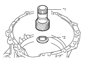
*1 Rear Planetary Sun Gear Assembly *2 Thrust Bearing Race Install the thrust bearing race and rear planetary sun gear assembly to the automatic transmission case sub-assembly.
Standard bearing and race diameter Item Inside Outside Thrust bearing race 30.0 mm (1.181 in.) 49.9 mm (1.965 in.) Note
-
Before installing the sun gear, apply ATF to sun gear bush's sliding surfaces. After the installation, check that the sun gear rotates smoothly.
-
Use a small amount of MP grease to make the thrust bearing race stay securely in place.
-
-
-
INSTALL NO. 2 BRAKE DISC
-
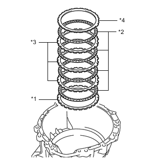
*1 No. 2 Brake Flange *2 No. 2 Brake Disc *3 No. 2 Brake Plate *4 Brake Plate Install the selected No. 2 brake flange, 4 No. 2 brake discs, 3 No. 2 brake plates and brake plate to the automatic transmission case sub-assembly.
Install in order *1 - *2 - *3 - *2 - *3 - *2 - *3 - *2 - *4 Tech Tips
Assemble the automatic transmission case sub-assembly, No. 2 brake flange, No. 2 brake plate and brake plate by aligning their grooves as shown in the illustration.
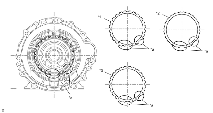
*1 No. 2 Brake Flange *2 Brake Plate *3 No. 2 Brake Plate - - *a Groove - - Note
Make sure that the discs, plates and the flange are installed in the correct order.
-
-
INSTALL NO. 1 ONE-WAY CLUTCH
-
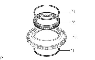
*1 Snap Ring *2 No. 1 One-way Clutch *3 one-way clutch outer race Install the No. 1 one-way clutch to the one-way clutch outer race with the 2 snap rings.
Note
Do not mistake the direction of the No. 1 one-way clutch.
-
-
INSPECT NO. 1 ONE-WAY CLUTCH
-
INSTALL ONE-WAY CLUTCH OUTER RACE WITH NO. 1 ONE-WAY CLUTCH
-
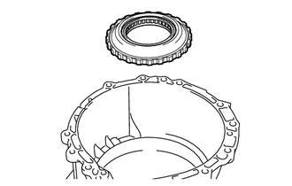
Install the one-way clutch outer race with No. 1 one-way clutch to the automatic transmission case sub-assembly.
-
Using SST, install the snap ring to the automatic transmission case sub-assembly.
- SST
- 09350-30020 ( 09350-07060 )
Note
-
Install the snap ring so that its tapered face is facing the front side of the automatic transmission case sub-assembly.
-
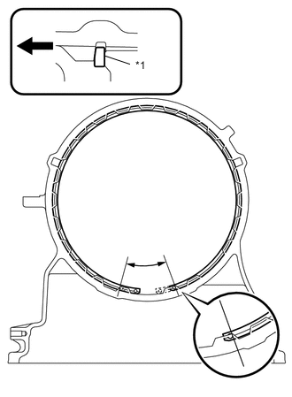
*1 Snap Ring 
Front Side Install the snap ring so that its gap end is within the range shown in the illustration.
-
-
INSTALL SUN GEAR INPUT DRUM SUB-ASSEMBLY
-
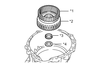
*1 Sun Gear Input Drum Sub-assembly *2 Thrust Needle Roller Bearing *3 Thrust Bearing Race Install the thrust bearing race, thrust needle roller bearing and sun gear input drum sub-assembly.
Standard bearing and race diameter Item Inside Outside Thrust bearing race 72.7 mm (2.858 in.) 89.2 mm (3.512 in.) Thrust needle roller bearing 71.9 mm (2.831 in.) 85.6 mm (3.370 in.) Note
-
Before installing the sun gear input drum sub-assembly, apply ATF to the sun gear input drum sub-assembly bush's sliding surfaces. After the installation, check that the sun gear input drum sub-assembly rotates smoothly.
-
Use a small amount of MP grease to make the thrust needle roller bearing and thrust bearing race stay securely in place.
-
-
-
INSTALL FORWARD CLUTCH PISTON
-
Coat 2 new O-rings with ATF, and install it to the forward clutch piston.
-
*1 Forward Clutch Piston Install the forward clutch piston to the forward clutch drum sub-assembly.
-
Coat a new O-ring with ATF, and install it to the No. 1 clutch balancer.
-
*1 No. 1 Clutch Balancer *2 Forward Clutch Return Spring Sub-assembly Install the forward clutch return spring sub-assembly and No. 1 clutch balancer to the forward clutch drum sub-assembly.
-
Place SST on the No. 1 clutch balancer, and compress the No. 1 clutch balancer with a press.
- SST
- 09380-50010 ( 09381-05020 )
-
Using SST, install the snap ring.
- SST
- 09350-30020 ( 09350-07070 )
Note
-
Be sure that the end gap of the snap ring is not aligned with the spring retainer claw.
-
Stop pressing when the balancer is lowered to the place 1 to 2 mm (0.039 to 0.078 in.) from the snap ring groove to prevent spring sheet deformation.
-
Do not expand the snap ring excessively.
-
-
INSTALL FORWARD MULTIPLE CLUTCH DISC
-
*1 Clutch Cushion Plate *2 Forward Multiple Clutch Plate *3 Forward Multiple Clutch Disc *4 Forward Clutch Flange Install the clutch cushion plate, 5 forward multiple clutch plates, 5 forward multiple clutch discs and forward clutch flange to the forward clutch drum sub-assembly.
Install in order *1 - *2 - *3 - *2 - *3 - *2 - *3 - *2 - *3 - *2 - *3 - *4 Note
-
Assemble the clutch cushion plate by facing its marked side towards the forward multiple clutch plates.
-
Make sure that the clutch cushion plate, forward multiple clutch discs, forward multiple clutch plates and the forward clutch flange are installed in the correct order.
-
-
Install the snap ring to the forward clutch drum sub-assembly.
-
-
INSPECT PACK CLEARANCE OF FORWARD MULTIPLE CLUTCH
-
INSTALL FRONT PLANETARY RING GEAR
-
*1 Rear Planetary Ring Gear *2 Snap Ring *3 Forward Multiple Disc Clutch Assembly Install the snap ring to the groove of forward multiple disc clutch assembly.
-
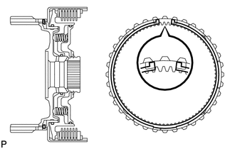
Using needle-nose pliers, attach the snap ring to install the front planetary ring gear to the forward multiple disc clutch assembly.
Note
Check that the snap ring is securely fit into the groove by looking through the front planetary ring gear slots on both sides.
-
-
INSTALL MULTIPLE DISC CLUTCH HUB
-
*1 Multiple Disc Clutch Hub *2 Thrust Needle Roller Bearing *3 Thrust Bearing Race *4 Forward Multiple Disc Clutch Assembly Install the thrust needle roller bearing, thrust bearing race and multiple disc clutch hub to the forward multiple disc clutch assembly.
Standard bearing and race diameter Item Inside Outside Thrust needle roller bearing 34.5 mm (1.358 in.) 49.4 mm (1.945 in.) Thrust bearing race 36.6 mm (1.441 in.) 51.9 mm (2.043 in.) Note
Use a small amount of MP grease to make the thrust needle roller bearing and thrust bearing race stay securely in place.
-
-
INSTALL FORWARD MULTIPLE DISC CLUTCH ASSEMBLY WITH FRONT PLANETARY RING GEAR AND MULTIPLE DISC CLUTCH HUB
-
*1 Front Planetary Ring Gear *2 Forward Multiple Disc Clutch Assembly *3 Thrust Bearing Race *4 Thrust Needle Roller Bearing Install the thrust bearing race, thrust needle roller bearing and forward multiple disc clutch assembly with front planetary ring gear and multiple disc clutch hub to the automatic transmission case sub-assembly.
Standard bearing and race diameter Item Inside Outside Thrust needle roller bearing 47.0 mm (1.850 in.) 61.9 mm (2.437 in.) Thrust bearing race 46.5 mm (1.831 in.) 60.1 mm (2.366 in.) Note
-
Before installing the forward multiple disc clutch assembly, apply ATF to forward multiple disc clutch assembly bush's sliding surfaces. After the installation, check that the forward multiple disc clutch assembly rotates smoothly.
-
Use a small amount of MP grease to make the thrust needle roller bearing and thrust needle roller bearing race stay securely in place.
-
-
-
INSTALL OVERDRIVE DIRECT CLUTCH PISTON SUB-ASSEMBLY
-
Coat a new O-ring with ATF, and install it to the overdrive direct clutch drum sub-assembly.
-
Coat a new O-ring with ATF, and install it to the overdrive direct clutch piston sub-assembly.
-
*1 Overdrive Direct Clutch Piston Sub-assembly Install the overdrive direct clutch piston sub-assembly to the overdrive direct clutch drum sub-assembly.
-
Coat a new O-ring with ATF, and install it to the No. 3 clutch balancer.
-
*1 No. 3 Clutch Balancer *2 Overdrive Clutch Return Spring Sub-assembly Install the overdrive clutch return spring sub-assembly and overdrive direct clutch balancer to the No. 3 clutch drum sub-assembly.
-
Place SST on the No. 3 clutch balancer, and compress the No. 3 clutch balancer with a press.
- SST
- 09380-50010 ( 09381-05020 )
-
Using SST, install the snap ring.
- SST
- 09350-30020 ( 09350-07070 )
Note
-
Be sure that the end gap of the snap ring is not aligned with the spring retainer claw.
-
Stop pressing when the balancer is lowered to the place 1 to 2 mm (0.039 to 0.078 in.) from the snap ring groove to prevent spring sheet deformation.
-
Do not expand the snap ring excessively.
-
-
INSTALL REVERSE CLUTCH DRUM SUB-ASSEMBLY
-
*1 Reverse Clutch Drum Sub-assembly Coat 3 new O-rings with ATF, and install them to the reverse clutch drum sub-assembly.
-
Install the reverse clutch drum sub-assembly to the overdrive direct clutch drum sub-assembly.
-
-
INSTALL REVERSE CLUTCH PISTON
-
*1 Reverse Clutch Piston Coat a new O-ring with ATF, and install it to the reverse clutch piston.
-
Install the reverse clutch piston to the overdrive direct clutch drum sub-assembly.
-
*1 Reverse Clutch Balancer *2 Reverse Clutch Return Spring Sub-assembly Install the reverse clutch return spring sub-assembly and reverse clutch balancer.
-
Place SST on the reverse clutch balancer, and compress the reverse clutch balancer with a press.
- SST
- 09380-50010 ( 09381-05020 )
-
Using SST, install the snap ring.
- SST
- 09350-30020 ( 09350-07070 )
Note
-
Be sure that the end gap of the snap ring is not aligned with the spring retainer claw.
-
Stop pressing when the balancer is lowered to the place 1 to 2 mm (0.039 to 0.078 in.) from the snap ring groove to prevent spring sheet deformation.
-
Do not expand the snap ring excessively.
-
-
INSTALL REVERSE CLUTCH DISC
-
*1 Reverse Clutch Flange *2 Reverse Clutch Disc *3 Reverse Clutch Plate Install the 5 reverse clutch plates, 5 reverse clutch discs and reverse clutch flange to the reverse clutch drum sub-assembly.
Install in order *1 - *2 - *1 - *2 - *1 - *2 - *1 - *2 - *1 - *2 - *3 Note
Make sure that the reverse clutch discs, reverse clutch plates and the reverse clutch flange are installed in the correct order.
-
Install the snap ring to the reverse clutch drum sub-assembly.
-
-
INSPECT PACK CLEARANCE OF REVERSE CLUTCH
-
INSTALL NO. 3 CLUTCH DISC
-
*1 No. 3 Clutch Plate *2 No. 3 Clutch Disc *3 No. 3 Clutch Flange Install the 4 No. 3 clutch plates, 4 No. 3 clutch discs and No. 3 clutch flange to the No. 3 clutch drum sub-assembly.
Install in order *1 - *2 - *1 - *2 - *1 - *2 - *1 - *2 - *3 Note
Make sure that the No. 3 clutch discs, No. 3 clutch plates and the No. 3 clutch flange are installed in the correct order.
-
Install the snap ring to the No. 3 clutch drum sub-assembly.
-
-
INSPECT PACK CLEARANCE OF NO. 3 CLUTCH
-
INSTALL FRONT PLANETARY GEAR ASSEMBLY
-
*1 Front Planetary Gear Thrust Needle Roller Bearing Install the front planetary gear thrust needle roller bearing to the front planetary gear assembly.
-
*1 Front Planetary Gear Shaft Snap Ring Coat 2 new front planetary gear shaft snap rings with ATF, and install them to the front planetary gear assembly.
Note
Do not expand the front planetary gear shaft snap ring ends excessively.
-
*1 Front Planetary Gear Shaft Snap Ring Coat 3 new front planetary gear shaft snap rings with ATF, and install them to the front planetary gear assembly.
Note
Do not expand the front planetary gear shaft snap ring ends excessively.
-
*1 Planetary Carrier Thrust Washer Install the planetary carrier thrust washer to the front planetary gear assembly.
Note
Use a small amount of MP grease to make the planetary carrier thrust washer stay securely in place.
-
*1 Planetary Sun Gear Install the front planetary sun gear assembly to the front planetary gear assembly.
-
Assemble the front planetary gear assembly with the front planetary sun gear to the overdrive and reverse multiple disc clutch assembly.
-
-
INSPECT PACK CLEARANCE OF NO. 1 BRAKE
-
INSTALL OVERDRIVE AND REVERSE MULTIPLE DISC CLUTCH ASSEMBLY WITH FRONT PLANETARY GEAR ASSEMBLY
-
*1 Thrust Needle Roller Bearing *2 Thrust Bearing Race Install the thrust bearing race, thrust needle bearing, overdrive and reverse multiple disc clutch assembly with front planetary gear assembly to the automatic transmission case sub-assembly.
Standard bearing and race diameter Item Inside Outside Thrust needle roller bearing 44.0 mm (1.732 in.) 62.0 mm (2.441 in.) Thrust bearing race 36.2 mm (1.425 in.) 58.2 mm (2.291 in.) Note
-
Before installing the overdrive and reverse multiple clutch, apply ATF to the No. 3 clutch drum bush's sliding surfaces. After the installation, check that the No. 3 clutch drum rotates smoothly.
-
Use a small amount of MP grease to make the thrust bearing and thrust bearing race stay securely in place.
-
-
-
INSTALL NO. 1 BRAKE DISC
-
*1 No. 1 Brake Flange *2 No. 1 Brake Disc *3 No. 1 Brake Plate Install the selected No. 1 brake flange, 4 No. 1 brake discs and 4 No. 1 brake plates to the automatic transmission case sub-assembly.
Install in order *1 - *2 - *3 - *2 - *3 - *2 - *3 - *2 - *3 Note
Make sure that the No. 1 brake discs, No. 1 brake plates and the No. 1 brake flange are installed in the correct order.
-
-
INSTALL OIL PUMP ASSEMBLY
-
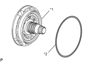
*1 Oil Pump Assembly *2 O-ring Coat a new O-ring with ATF, and install it to the oil pump assembly.
-
Place the oil pump assembly through the input shaft, and align the bolt holes of the oil pump assembly with the automatic transmission case sub-assembly.
-
Hold the input shaft, and lightly press the oil pump body to slide the oil seal rings into the No. 3 clutch drum sub-assembly.
-
Install the 11 bolts.
- Torque:
- 21.1 N*m { 215 kgf*cm, 16 ft.*lbf }
Note
-
Make sure to apply seal packing to the flanges of the bolts.
Seal packing Toyota Genuine Seal Packing 1281,Three Bond 1281 or equivalent -
Do not allow seal packing to contact the bolts' threads.
-
During installation, do not allow oil to contact the bolts or the surface of the oil pump body.
-
-
INSTALL INDIVIDUAL PISTON OPERATION
-
INSTALL MANUAL VALVE LEVER SHAFT OIL SEAL
-
Using SST and a hammer, tap in a new manual valve lever shaft oil seal.
- SST
- 09350-30020 ( 09350-07110 )
Standard depth -0.3 to 0.3 mm (-0.012 to 0.011 in.) -
Coat the lip of the manual valve lever shaft oil seal with MP grease.
-
-
INSTALL MANUAL VALVE LEVER SUB-ASSEMBLY
-
*1 Spacer Install a new spacer to the manual valve lever sub-assembly.
-
Install the manual valve lever shaft to the automatic transmission case sub-assembly through the manual valve lever sub-assembly.
-
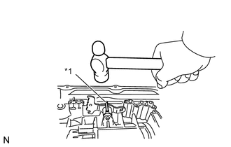
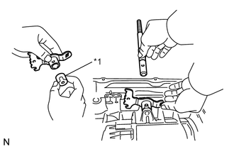
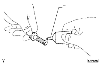
*1 Spring Pin Using a hammer, tap in a new spring pin.
-
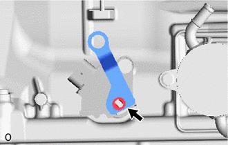
Align the manual valve lever sub-assembly indentation with the spacer hole, and stake them together with a punch.
-
Make sure that the shaft rotates smoothly.
-
-
INSTALL PARKING LOCK PAWL SHAFT
-
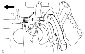
*1 Parking Lock Pawl *2 Parking Lock Pawl Shaft *3 Spring *4 E-ring Front Side Install the E-ring to the parking lock pawl shaft.
-
Install the parking lock pawl, parking lock pawl shaft and spring.
-
-
INSTALL PARKING LOCK ROD SUB-ASSEMBLY
-
Connect the parking lock rod sub-assembly to the manual valve lever sub-assembly.
-
-
INSTALL PARKING LOCK PAWL BRACKET
-

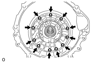
Place the parking lock pawl bracket onto the automatic transmission case sub-assembly. Loosely install the 3 bolts, and then tighten them in the order shown in the illustration.
- Torque:
- 18 N*m { 184 kgf*cm, 13 ft.*lbf }
-
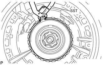
Shift the manual valve lever to the P position, and confirm that the output shaft is correctly locked up by the parking lock pawl.
-
-
INSTALL AUTOMATIC TRANSMISSION CASE PLUG
-
Coat a new O-ring with ATF, and install it to the automatic transmission case plug.
-
Install the automatic transmission case plug to the automatic transmission case sub-assembly.
- Torque:
- 80 N*m { 816 kgf*cm, 59 ft.*lbf }
-
-
INSTALL TRANSMISSION REVOLUTION SENSOR
-
*1 Transmission Revolution Sensor NT *2 Transmission Revolution Sensor NC3 *3 Transmission Revolution Sensor SP2 Coat a new O-ring with ATF and install it to the transmission revolution sensor NT.
-
Using ''TORX'' socket wrench T30, install the transmission revolution sensor NT with the bolt.
- Torque:
- 6.8 N*m { 69 kgf*cm, 60 in.*lbf }
-
Install the transmission revolution sensor SP2 and NC3 with the 2 bolts.
- Torque:
- 5.4 N*m { 55 kgf*cm, 48 in.*lbf }
-
-
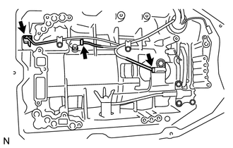
INSTALL TRANSMISSION WIRE
-
Install the 2 valve body wire harness clamps to the automatic transmission case sub-assembly with the 2 bolts.
- Torque:
- 5.4 N*m { 55 kgf*cm, 48 in.*lbf }
-
Coat a new O-ring with ATF.
-
Install the O-ring to the transmission wire connector.
-
Install the transmission wire.
-
Install the bolt.
- Torque:
- 5.4 N*m { 55 kgf*cm, 48 in.*lbf }
-
Connect the 3 connectors to the transmission revolution sensor.
-
-
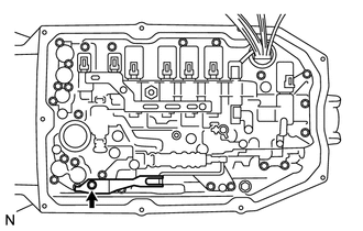
INSTALL CHECK BALL BODY
-
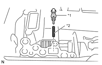
*1 Check Ball Body *2 Spring Install the spring and check ball body.
-
-
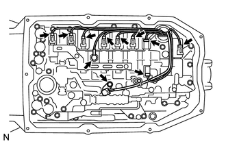
INSTALL TRANSMISSION VALVE BODY ASSEMBLY
-
Install the spring and check ball body.
-
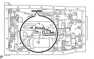
*1 Manual Valve Connecting Rod *2 Manual Valve Lever Sub-assembly Align the groove of the manual valve lever sub-assembly with the manual valve connecting rod.
-
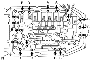
Install the transmission valve body assembly with the 17 bolts.
- Torque:
- 11 N*m { 112 kgf*cm, 8 ft.*lbf }
Tech Tips
Each bolt length is indicated below.
Bolt length Bolt A 21 mm (0.8268 in.) Bolt B 31 mm (1.2205 in.) Bolt C 64 mm (2.5197 in.) -
Install the detent spring and detent spring cover with the bolt.
- Torque:
- 10 N*m { 102 kgf*cm, 7 ft.*lbf }
Note
Make sure to install the detent spring so that its roller is perpendicularly at the center of the manual valve lever.
-
Connect the 9 connectors to the solenoid valves.
-
Connect the oil pressure switch connector.
-
Coat a new O-ring with ATF and install it to the ATF temperature sensor.
-
Install the ATF temperature sensor and lock plate with the bolt.
- Torque:
- 10 N*m { 102 kgf*cm, 7 ft.*lbf }
-
-
INSTALL VALVE BODY OIL STRAINER ASSEMBLY
-
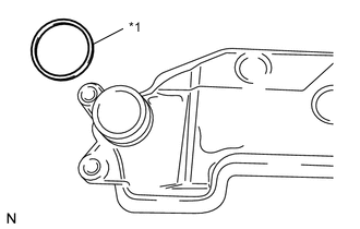
*1 O-ring Coat a new O-ring with ATF and install it to the valve body oil strainer assembly.
Note
Ensure that the O-ring is not twisted or pinched.
-
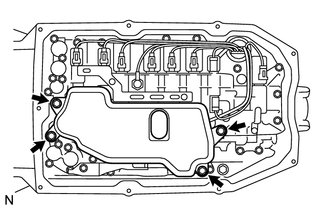
Install the valve body oil strainer assembly to the transmission valve body assembly with the 4 bolts.
- Torque:
- 10 N*m { 102 kgf*cm, 7 ft.*lbf }
-
-
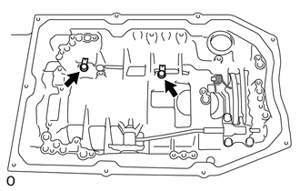
INSTALL AUTOMATIC TRANSMISSION OIL PAN SUB-ASSEMBLY
-
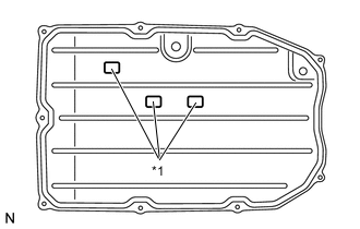
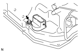
*1 Transmission Oil Cleaner Magnet Install the 3 transmission oil cleaner magnets to the automatic transmission oil pan sub-assembly.
-
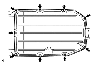
Install a new automatic transmission oil pan gasket and the automatic transmission oil pan sub-assembly to the automatic transmission case sub-assembly with the 9 bolts.
- Torque:
- 7.4 N*m { 75 kgf*cm, 65 in.*lbf }
Note
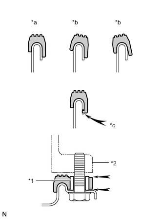
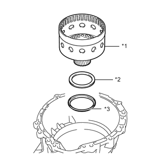
*1 Sleeve *2 Automatic Transmission Case Sub-assembly *a Correct *b Incorrect *c Protrusion
-
Make sure that there is no oil or foreign matter on the gasket seal surface and automatic transmission oil pan sub-assembly contact surface.
-
Install the gasket so that there is no slack in the gasket, and that the seal surface's entire circumference is level.
-
Make sure that the 9 gasket drop prevention protrusions are set on the automatic transmission oil pan sub-assembly.
-
When tightening the automatic transmission oil pan sub-assembly, make sure that the gasket is not pinched between the gasket tightening area's sleeve and the transmission's seal surface.
-
-
INSTALL BREATHER PLUG HOSE
-
Install the O-ring to the breather plug hose.
-
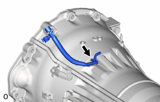
Install the breather plug hose to the automatic transmission case sub-assembly.
-
-
INSTALL TRANSMISSION OIL COOLER (w/ ATF Warmer)
-
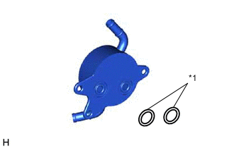
*1 O-ring Coat 2 new O-rings with ATF, and install them to the transmission oil cooler.
-
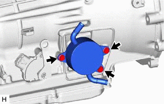
Install the transmission oil cooler to the automatic transmission case sub-assembly with the 3 bolts.
- Torque:
- 21 N*m { 214 kgf*cm, 15 ft.*lbf }
-
-
INSTALL OIL COOLER UNION SUB-ASSEMBLY (w/o ATF Warmer)
-
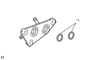
*1 O-ring Coat 2 new O-rings with ATF, and install them to the oil cooler union sub-assembly.
-
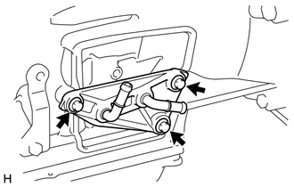
Install the oil cooler union sub-assembly to the automatic transmission case sub-assembly with the 3 bolts.
- Torque:
- 21 N*m { 214 kgf*cm, 15 ft.*lbf }
-
-
INSTALL PARK/NEUTRAL POSITION SWITCH ASSEMBLY
Tech Tips
Make sure that the manual valve lever shaft has not been rotated prior to installing the park/neutral position switch assembly as the detent spring may become detached from the manual valve lever shaft.
-
Clean the bolt and the bolt hole.
-
*1 Adhesive 1344 Apply adhesive to 2 or 3 threads on the end of the bolt.
Adhesive Toyota Genuine Adhesive 1344, Three Bond 1344 or equivalent Note
Install the bolt within 3 minutes of applying adhesive.
-
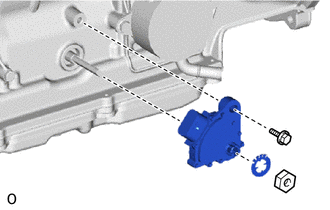
Temporarily install the park/neutral position switch assembly to the automatic transmission assembly with the bolt.
Tech Tips
Tighten the bolt to the specified torque when adjusting the park/neutral position switch assembly.
-
Install a new nut stopper and the lock nut to the park/neutral position switch assembly.
- Torque:
- 6.9 N*m { 70 kgf*cm, 61 in.*lbf }
-
Temporarily install the transmission control shaft lever RH to the park/neutral position switch assembly with the spring washer and nut.
Tech Tips
Tighten the nut to the specified torque when adjusting the park/neutral position switch assembly.
-
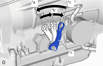
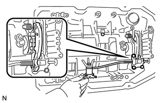
*1 Transmission Control Shaft Lever RH *a P *b R *c N Turn the transmission control shaft lever RH counterclockwise until it stops, then turn it clockwise 2 notches.
-
Remove the nut, spring washer and transmission control shaft lever RH from the park/neutral position switch assembly.
-
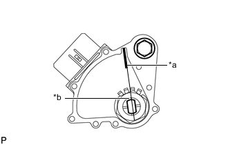
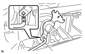
*a Neutral Basic Line *b Groove Align the neutral basic line with the groove as shown in the illustration.
-
Hold the park/neutral position switch assembly in that position and tighten the bolt.
- Torque:
- 12.8 N*m { 131 kgf*cm, 9 ft.*lbf }
-
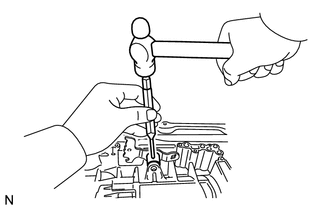
Using a screwdriver, stake the lock nut with the stopper plate.
-
-
INSTALL TRANSMISSION CONTROL SHAFT LEVER RH
-
Install the transmission control shaft lever RH to the park/neutral position switch assembly with the spring washer and nut.
- Torque:
- 15.7 N*m { 160 kgf*cm, 12 ft.*lbf }
-