AUTOMATIC TRANSMISSION UNIT(for 2GR) INSPECTION

PROCEDURE
-
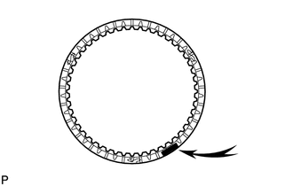
INSPECT NO. 1 BRAKE DISC
-
Check whether the sliding surfaces of the No. 1 brake discs, No. 1 brake plates and the No. 1 brake flange are worn or burnt.
If necessary, replace them.
Note
-
If the linings of the No. 1 brake discs are peeled off or discolored, or if any part of the printed numbers is damaged, replace all the No. 1 brake discs.
-
Before assembling new No. 1 brake discs, soak them in ATF for at least 2 hours.
-
-
-
INSPECT FRONT PLANETARY GEAR ASSEMBLY
-
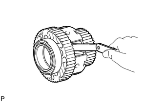
Using a feeler gauge, measure the front planetary gear pinion thrust clearance.
Standard clearance 0.2 to 0.6 mm (0.0079 to 0.0236 in.)
-
If the inside diameter is more than the standard inside diameter, replace the rear planetary gear assembly.
-
-
-
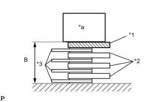
INSPECT PACK CLEARANCE OF NO. 1 BRAKE
-
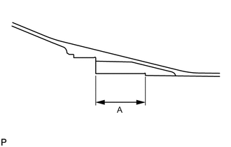
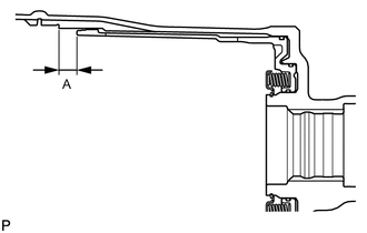
Using a vernier caliper, measure dimension A (from the step of the oil pump installation surface of the automatic transmission case sub-assembly to the step of the No. 1 brake flange installation surface) in the illustration, and calculate the average.
Tech Tips
Dimension A = 59.77 to 60.03 mm (2.3532 to 2.3633 in.)
-
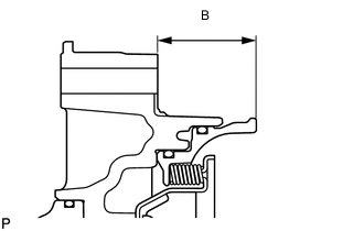
Using a vernier caliper, measure dimension B (from the flange face of the oil pump assembly to the tip of the No. 1 brake piston) in the illustration, and calculate the average.
Tech Tips
Dimension B = 34.636 to 34.964 mm (1.3637 to 1.3765 in.)
-
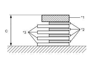
*1 No. 1 Brake Flange *2 No. 1 Brake Disc *3 No. 1 Brake Plate Using a vernier caliper, assemble the 4 No. 1 brake plates, 4 No. 1 brake discs, and No. 1 brake flange, and measure dimension C in the illustration, and calculate the average.
Tech Tips
-
Dimension C = 19.41 to 21.11 mm (0.7642 to 0.8311 in.)
-
Pack clearance = Dimension A - Dimension B - Dimension C
Pack clearance 0.75 to 1.05 mm (0.0296 to 0.0413 in.) -
-
If the pack clearance is outside the standard range, select and install a No. 1 brake flange that brings the pack clearance to be within the standard range.
Tech Tips
There are 9 types of No. 1 brake flanges that can be used to adjust the pack clearance. Select the one with the most appropriate thickness.
Flange thickness Part No. Mark Thickness 35676-50070 0 4.45 to 4.55 mm (0.1752 to 0.1791 in.) 35676-50080 1 4.55 to 4.65 mm (0.1791 to 0.1831 in.) 35676-50090 2 4.65 to 4.75 mm (0.1831 to 0.1870 in.) 35676-50100 3 4.75 to 4.85 mm (0.1870 to 0.1909 in.) 35676-50110 4 4.85 to 4.95 mm (0.1909 to 0.1949 in.) 35676-50120 5 4.95 to 5.05 mm (0.1949 to 0.1988 in.) 35676-50130 6 5.05 to 5.15 mm (0.1988 to 0.2028 in.) 35676-50140 7 5.15 to 5.25 mm (0.2028 to 0.2067 in.) 35676-50150 8 5.25 to 5.35 mm (0.2067 to 0.2106 in.)
-
-
INSPECT NO. 3 CLUTCH DISC
-
Check whether the sliding surfaces of the No. 3 Clutch discs, No. 3 Clutch plates and the No. 3 Clutch flange are worn or burnt.
If necessary, replace them.
Note
Before assembling new No. 3 Clutch discs, soak them in ATF for at least 2 hours.
-
-
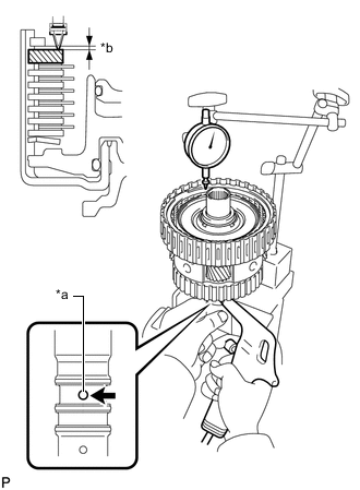
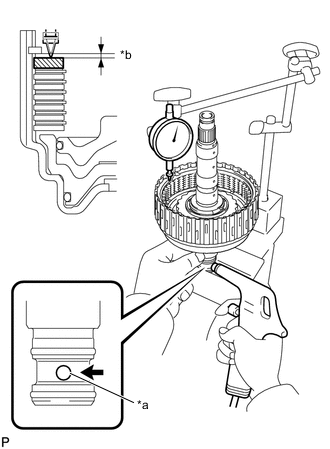
INSPECT PACK CLEARANCE OF NO. 3 CLUTCH
-
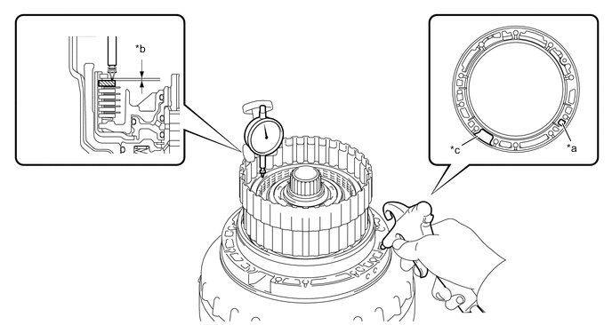
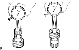
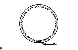
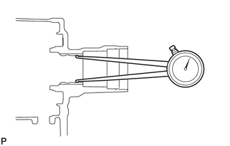
Using a dial indicator, measure the moving distance (distance A) of the No. 3 clutch flange at both ends across the diameter while blowing compressed air (196 kPa, 2.0 kgf/cm2, 28 psi) from the oil hole as shown in the illustration, and calculate the average.
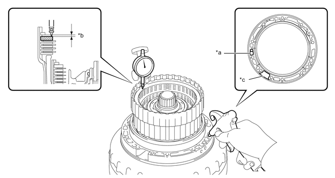
*a Oil Hole *b Distance A *c Speed Sensor Hole - - Pack clearance 0.4 to 0.7 mm (0.0158 to 0.0275 in.) -
If the pack clearance is outside the standard range, select and install a No. 3 clutch flange that brings the pack clearance within the standard range.
Tech Tips
There are 7 types of No. 3 clutch flanges that can be used to adjust the pack clearance. Select the one with the most appropriate thickness.
Flange thickness Part No. Mark Thickness 34615-50060 0 3.95 to 4.05 mm (0.1555 to 0.1594 in.) 34615-50070 1 4.05 to 4.15 mm (0.1594 to 0.1634 in.) 34615-50080 2 4.15 to 4.25 mm (0.1634 to 0.1673 in.) 34615-50090 3 4.25 to 4.35 mm (0.1673 to 0.1713 in.) 34615-50100 4 4.35 to 4.45 mm (0.1713 to 0.1752 in.) 34615-50110 5 4.45 to 4.55 mm (0.1752 to 0.1791 in.) 34615-50120 6 4.55 to 4.65 mm (0.1791 to 0.1831 in.)
-
-
INSPECT REVERSE CLUTCH DISC
-
Check whether the sliding surfaces of the reveres clutch discs, reveres clutch plates and the reveres clutch flange are worn or burnt.
If necessary, replace them.
Note
-
If the linings of the reveres clutch discs are peeled off or discolored, or if any part of the printed numbers is damaged, replace all the reveres clutch discs.
-
Before assembling new reveres clutch discs, soak them in ATF for at least 2 hours.
-
-
-
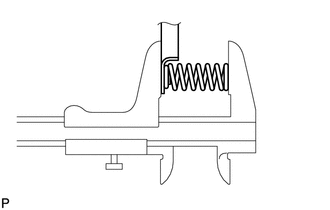
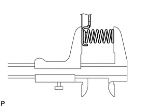
INSPECT REVERSE CLUTCH RETURN SPRING SUB-ASSEMBLY
-
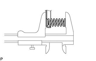
Using a vernier caliper, measure the free length of the spring together with the spring seat.
Standard free length 22.21 mm (0.8744 in.)
-
If the free length is shorter than the standard free length, replace the reverse clutch return spring sub-assembly.
-
-
-
INSPECT PACK CLEARANCE OF REVERSE CLUTCH
-
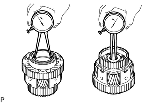
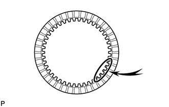
Using a dial indicator, measure the moving distance (distance A) of the reverse clutch flange at both ends across the diameter while blowing compressed air (196 kPa, 2.0 kgf/cm2, 28 psi) from the oil hole as shown in the illustration, and calculate the average.
*a Oil Hole *b Distance A *c Speed Sensor Hole - - Pack clearance 0.5 to 0.8 mm (0.0197 to 0.0314 in.) -
If the pack clearance is outside the standard range, select and install a reverse clutch flange that brings the pack clearance within the standard range.
Tech Tips
There are 9 types of reverse clutch flanges that can be used to adjust the pack clearance. Select the one with the most appropriate thickness.
Flange thickness Part No. Mark Thickness 35649-50080 0 2.95 to 3.05 mm (0.1161 to 0.1201 in.) 35649-50090 1 3.05 to 3.15 mm (0.1201 to 0.1240 in.) 35649-50100 2 3.15 to 3.25 mm (0.1240 to 0.1280 in.) 35649-50110 3 3.25 to 3.35 mm (0.1280 to 0.1319 in.) 35649-50120 4 3.35 to 3.45 mm (0.1319 to 0.1358 in.) 35649-50130 5 3.45 to 3.55 mm (0.1358 to 0.1398 in.) 35649-50140 6 3.55 to 3.65 mm (0.1398 to 0.1437 in.) 35649-50150 7 3.65 to 3.75 mm (0.1437 to 0.1476 in.) 35649-50160 8 3.75 to 3.85 mm (0.1476 to 0.1516 in.)
-
-
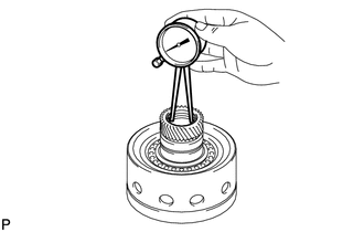
INSPECT OVERDRIVE CLUTCH RETURN SPRING SUB-ASSEMBLY
-
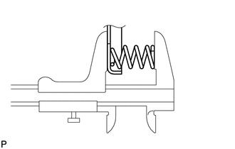
Using a vernier caliper, measure the free length of the spring together with the spring seat.
Standard free length 21.09 mm (0.8303 in.)
-
If the free length is shorter than the standard free length, replace the overdrive clutch return spring sub-assembly.
-
-
-
INSPECT OVERDRIVE DIRECT CLUTCH DRUM SUB-ASSEMBLY
-
Using a caliper gauge, measure the inside diameter of the overdrive direct clutch drum sub-assembly bush.
Standard inside diameter for front side 67.40 to 67.44 mm (2.6536 to 2.6551 in.) Standard inside diameter for rear side 55.62 to 55.64 mm (2.1898 to 2.1905 in.)
-
If the inside diameter is not as specified, replace the overdrive direct clutch drum sub-assembly.
-
-
-
INSPECT FORWARD MULTIPLE CLUTCH DISC
-
Check whether the sliding surfaces of the forward multiple clutch discs, forward multiple clutch plates, forward clutch flange and the clutch cushion plate are worn or burnt.
If necessary, replace them.
Note
-
If the linings of the forward multiple clutch discs are peeled off or discolored, or if any part of the printed numbers is damaged, replace all the forward multiple clutch discs.
-
Before assembling new forward multiple clutch discs, soak them in ATF for at least 2 hours.
-
-
-
INSPECT FORWARD CLUTCH RETURN SPRING SUB-ASSEMBLY
-
Using a vernier caliper, measure the free length of the spring together with the spring seat.
Standard free length 20.82 mm (0.8197 in.)
-
If the free length is shorter than the standard free length, replace the forward clutch return spring sub-assembly.
-
-
-
INSPECT PACK CLEARANCE OF FORWARD MULTIPLE CLUTCH
-
Temporarily assemble the front planetary gear assembly to the forward clutch drum sub-assembly.
-
*a Oil Hole *b Distance A Using a dial indicator, measure the moving distance (distance A) of the forward clutch flange at both ends across the diameter while blowing compressed air (196 kPa, 2.0 kgf/cm2, 28 psi) from the oil hole as shown in the illustration, and calculate the average.
Pack clearance 0.90 to 1.20 mm (0.0355 to 0.0472 in.) -
If the pack clearance is outside the standard range, select and install a forward clutch flange that brings the pack clearance within the standard range.
Tech Tips
There are 9 types of forward clutch flanges that can be used to adjust the pack clearance. Select the one with the most appropriate thickness.
Flange thickness Part No. Mark Thickness 35635-50090 0 4.35 to 4.45 mm (0.1713 to 0.1752 in.) 35635-50100 1 4.45 to 4.55 mm (0.1752 to 0.1791 in.) 35635-50110 2 4.55 to 4.65 mm (0.1791 to 0.1831 in.) 35635-50120 3 4.65 to 4.75 mm (0.1831 to 0.1870 in.) 35635-50130 4 4.75 to 4.85 mm (0.1870 to 0.1909 in.) 35635-50140 5 4.85 to 4.95 mm (0.1909 to 0.1949 in.) 35635-50150 6 4.95 to 5.05 mm (0.1949 to 0.1988 in.) 35635-50160 7 5.05 to 5.15 mm (0.1988 to 0.2029 in.) 35635-50170 8 5.15 to 5.25 mm (0.2029 to 0.2067 in.) -
Remove the front planetary gear assembly.
-
-
INSPECT FORWARD CLUTCH DRUM SUB-ASSEMBLY
-

Using a caliper gauge, measure the inside diameter of the forward clutch drum bush.
Standard inside diameter 33.200 to 33.225 mm (1.3071 to 1.3080 in.)
-
If the inside diameter is not as specified, replace the forward clutch drum sub-assembly.
-
-
-
INSPECT SUN GEAR INPUT DRUM SUB-ASSEMBLY
-
Using a caliper gauge, measure the inside diameter of the sun gear input drum bush.
Standard inside diameter 45.075 to 45.100 mm (1.7747 to 1.7755 in.)
-
If the inside diameter is not as specified, replace the sun gear input drum sub-assembly.
-
-
-
INSPECT REAR PLANETARY SUN GEAR ASSEMBLY
-
Using a caliper gauge, measure the inside diameter of the rear planetary sun gear bush.
Standard inside diameter 28.700 to 28.721 mm (1.1300 to 1.1307 in.)
-
If the inside diameter is not as specified, replace the rear planetary sun gear assembly.
-
-
-
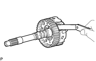
INSPECT REAR PLANETARY GEAR ASSEMBLY
-
Using a feeler gauge, measure the rear planetary gear pinion long and short thrust clearance.
Standard clearance 0.2 to 0.6 mm (0.0079 to 0.0236 in.)
-
If the clearance is not as specified, replace the rear planetary gear assembly.
-
-
Using a caliper gauge, measure the inside diameter of the rear planetary gear bush.
Standard inside diameter for front side 71.60 to 71.63 mm (2.8189 to 2.8200 in.) Standard inside diameter for rear side 28.700 to 28.721 mm (1.1300 to 1.1307 in.)
-
If the inside diameter is not as specified, replace the rear planetary gear assembly.
-
-
-
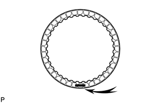
INSPECT NO. 1 ONE-WAY CLUTCH
-
Set the one-way clutch to the rear planetary gear assembly.
-
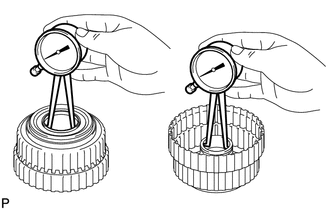
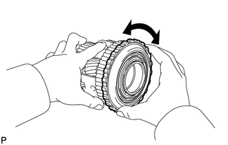
Hold the rear planetary gear assembly and turn the one-way clutch.
-
Check that the one-way clutch turns freely counterclockwise and locks clockwise.
-
If there is a problem with the one-way clutch, replace it.
-
-
-
INSPECT NO. 2 BRAKE DISC
-
Check whether the sliding surfaces of the No. 2 brake discs, No. 2 brake plates No. 2 brake flange and the brake plate are worn or burnt.
If necessary, replace them.
Note
-
If the linings of the No. 2 brake discs are peeled off or discolored, or if any part of the printed numbers is damaged, replace all the No. 2 brake discs.
-
Before assembling new discs, soak them in ATF for at least 2 hours.
-
-
-
INSPECT NO. 2 CLUTCH DISC
-
Check whether the sliding surfaces of the No. 2 clutch discs, No. 2 clutch plates and the No. 2 clutch flange are worn or burnt.
If necessary, replace them.
Note
Before assembling new No. 2 clutch discs, soak them in ATF for at least 2 hours.
-
-
INSPECT DIRECT CLUTCH RETURN SPRING SUB-ASSEMBLY
-
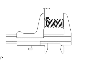
Using a vernier caliper, measure the free length of the spring together with the spring seat.
Standard free length 20.76 mm (0.8173 in.)
-
If the free length is shorter than the standard free length, replace the direct clutch return spring sub-assembly.
-
-
-
INSPECT PACK CLEARANCE OF NO. 2 BRAKE
-
Using a vernier caliper, measure dimension A (from the tip of the No. 2 brake piston to the step in the automatic transmission case sub-assembly) in the illustration, and calculate the average.
Tech Tips
Dimension A = 14.77 to 15.37 mm (0.5815 to 0.6051 in.)
-
*a Weight *1 No. 2 Brake Flange *2 No. 2 Brake Plate *3 No. 2 Brake Disc Using a vernier caliper, assemble the 4 No. 2 brakes discs, 3 No. 2 brake plates and No. 2 brake flange as shown in the illustration. Then with a weight fixture of 500 g (17.64 oz) or less placed on the flange, measure dimension B, and calculate the average.
Tech Tips
-
Dimension B = 13.16 to 14.76 mm (0.5182 to 0.5811 in.)
-
Pack clearance = Dimension A - Dimension B
Pack clearance 0.52 to 0.82 mm (0.0205 to 0.0322 in.) -
-
If the pack clearance is outside the standard range, select and install a No. 2 brake flange that brings the pack clearance to be within the standard range.
Tech Tips
There are 9 types of No. 2 brake flanges that can be used to adjust the pack clearance. Select the one with the most appropriate thickness.
Flange thickness Part No. Mark Thickness 35678-50010 0 1.95 to 2.05 mm (0.0768 to 0.0807 in.) 35678-50020 1 2.05 to 2.15 mm (0.0807 to 0.0846 in.) 35678-50030 2 2.15 to 2.25 mm (0.0846 to 0.0886 in.) 35678-50040 3 2.25 to 2.35 mm (0.0886 to 0.0925 in.) 35678-50050 4 2.35 to 2.45 mm (0.0925 to 0.0965 in.) 35678-50060 5 2.45 to 2.55 mm (0.0965 to 0.1004 in.) 35678-50070 6 2.55 to 2.65 mm (0.1004 to 0.1043 in.) 35678-50080 7 2.65 to 2.75 mm (0.1043 to 0.1083 in.) 35678-50090 8 2.75 to 2.85 mm (0.1083 to 0.1122 in.)
-
-
INSPECT PACK CLEARANCE OF NO. 2 CLUTCH
-
*a Oil Hole *b Distance A Using a dial indicator, measure the moving distance (distance A) of the No. 2 clutch flange at both ends across the diameter while blowing compressed air (196 kPa, 2.0 kgf/cm2, 28 psi) from the oil hole as shown in the illustration, and calculate the average.
Pack clearance 0.90 to 1.20 mm (0.0354 to 0.0472 in.) -
If the pack clearance is outside the standard range, select and install a No. 2 clutch flange that brings the pack clearance within the standard range.
Tech Tips
There are 9 types of No. 2 clutch flanges that can be used to adjust the pack clearance. Select the one with the most appropriate thickness.
Flange thickness Part No. Mark Thickness 35635-50181 40 3.95 to 4.05 mm (0.1555 to 0.1594 in.) 35635-50191 41 4.05 to 4.15 mm (0.1594 to 0.1634 in.) 35635-50201 42 4.15 to 4.25 mm (0.1634 to 0.1673 in.) 35635-50211 43 4.25 to 4.35 mm (0.1673 to 0.1713 in.) 35635-50221 44 4.35 to 4.45 mm (0.1713 to 0.1752 in.) 35635-50231 45 4.45 to 4.55 mm (0.1752 to 0.1791 in.) 35635-50241 46 4.55 to 4.65 mm (0.1791 to 0.1831 in.) 35635-50251 47 4.65 to 4.75 mm (0.1831 to 0.1870 in.) 35635-50261 48 4.75 to 4.85 mm (0.1870 to 0.1909 in.)
-
-
INSPECT 2ND BRAKE PISTON RETURN SPRING SUB-ASSEMBLY
-
Using a vernier caliper, measure the free length of the spring together with the spring seat.
Standard free length 23.36 mm (0.9197 in.)
-
If the free length is shorter than the standard free length, replace the 2nd brake piston return spring sub-assembly.
-
-
-
INSPECT INDIVIDUAL PISTON OPERATION
-
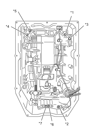
*1 Forward Multiple Clutch *2 No. 2 Clutch *3 No. 3 Clutch *4 Reverse Clutch *5 No. 1 Brake *6 No. 2 Brake (IN) *7 No. 2 Brake (OUT) Check the operating sound while applying compressed air into the oil holes indicated in the illustration.
-
-
INSPECT AUTOMATIC TRANSMISSION CASE SUB-ASSEMBLY
-
Using a caliper gauge, measure the inside diameter of the automatic transmission case sleeve bush.
Standard free length 49.070 to 49.155 mm (1.9319 to 1.9352 in.)
-
If the inside diameter is not as specified, replace the automatic transmission case sub-assembly.
-
-