AUTOMATIC TRANSMISSION ASSEMBLY(for 2GR) INSTALLATION

CAUTION / NOTICE / HINT
CAUTION:
The automatic transmission assembly is very heavy. Be sure to follow the procedure described in the repair manual, or the engine lifter may suddenly drop.
PROCEDURE
-
INSTALL TORQUE CONVERTER ASSEMBLY
-
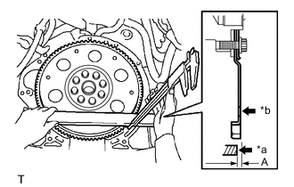
*a Engine Assembly Surface *b Drive Plate Surface Using a vernier caliper and straightedge, measure the dimension (A) between the automatic transmission assembly contact surface of the engine assembly and the torque converter assembly contact surface of the drive plate.
-

*a Matchmark Align the matchmark on the case with the one on the torque converter assembly and engage the splines of the input shaft with the turbine runner splines.
Note
Install the torque converter assembly to the input shaft while keeping it horizontal.
-
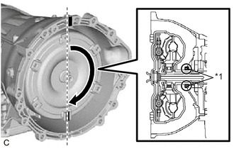
*1 Front Oil Pump Oil Seal Rotate the torque converter assembly approximately 180° and engage the splines of the stator shaft with the stator assembly.
Note
-
Do not damage the front oil pump oil seal.
-
Install the torque converter assembly to the input shaft while keeping it horizontal.
-
-
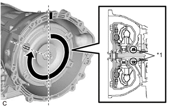
*1 Front Oil Pump Oil Seal Rotate the torque converter assembly approximately 180° again, align the matchmark on the torque converter assembly with the one on the case and insert the key of the torque converter assembly into the groove of the oil pump drive gear.
Note
-
Do not push the torque converter assembly excessively when rotating it.
-
Do not damage the front oil pump oil seal.
-
Install the torque converter assembly to the input shaft while keeping it horizontal.
-
-
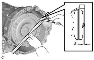
Using a vernier caliper and straightedge, measure the dimension (B) shown in the illustration and check that the dimension (B) is more than the dimension (A), which was measured in the previous step.
Standard A + 1 mm (0.0394 in.) or more Note
-
Make sure to deduct the thickness of the straightedge.
-
If the automatic transmission assembly is installed to the engine assembly with the torque converter assembly not sufficiently inserted, the torque converter assembly may be damaged.
-
-
-
INSTALL REAR ENGINE MOUNTING BRACKET
-
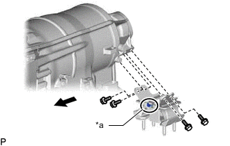
*a Claw 
Vehicle Front Install the rear engine mounting bracket to the automatic transmission assembly with the 4 bolts.
- Torque:
- 40 N*m { 408 kgf*cm, 30 ft.*lbf }
Tech Tips
Make sure that the claw is facing the front of the vehicle.
-
-
INSTALL AUTOMATIC TRANSMISSION ASSEMBLY
-
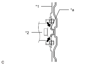
*1 Drive Plate *2 Crankshaft *a Torque Converter Assembly Centerpiece Clutch Spline Grease Apply clutch spline grease to the circumference of the part of the crankshaft that contacts the torque converter assembly centerpiece.
Clutch Spline Grease Toyota Genuine Clutch Spline Grease or equivalent Maximum Grease Amount Approximately 1 g (0.0353 oz) -
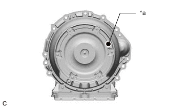
*a Mark Make sure that the mark is positioned as shown in the illustration.
-
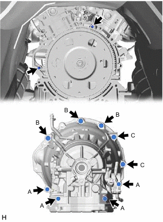
Confirm that the 2 knock pins are installed on the engine assembly and are not damaged.
-
While keeping the engine assembly and automatic transmission assembly horizontal, align the 2 knock pins with the holes in the automatic transmission assembly and install the 9 bolts.
- Torque:
- Bolt (A)
- 37 N*m { 377 kgf*cm, 27 ft.*lbf }
- Bolt (B), (C)
- 71 N*m { 724 kgf*cm, 52 ft.*lbf }
Note
-
When tightening the bolts, be sure that the contact surfaces of the engine assembly and the automatic transmission assembly are in close contact with one another.
-
Do not forcibly pry on the automatic transmission assembly.
-
Check that the torque converter assembly rotates.
-
Make sure not to pinch or damage any wire harness.
-
In order to protect the automatic transmission oil pan sub-assembly, place attachments on the transmission jack.
-
Make sure that the attachments and the automatic transmission oil pan sub-assembly are centered on the transmission jack.
-
To prevent the automatic transmission oil pan sub-assembly from deforming, do not place any attachments under the automatic transmission oil pan sub-assembly of the automatic transmission assembly.
-
Secure the automatic transmission assembly to the transmission jack using a belt, etc. to prevent it from falling.
Tech Tips
Bolt Length
-
Bolt (A): 43 mm (1.69 in.)
-
Bolt (B): 50 mm (1.97 in.)
-
Bolt (C): 70 mm (2.76 in.)
-
-
CONNECT WATER BY-PASS HOSE (w/ ATF Warmer)
-
Tilt down the automatic transmission assembly.
Note
Make sure that the cooling fan and fan shroud do not contact the engine assembly when tilting the automatic transmission assembly.
-
Connect the water by-pass hose and No. 2 water by-pass hose to the transmission oil cooler and slide the 2 clips to secure them.
-
Install the hose clamp to the automatic transmission assembly with the bolt.
- Torque:
- 20 N*m { 204 kgf*cm, 15 ft.*lbf }
-
-
CONNECT OIL COOLER TUBE SUB-ASSEMBLY (w/o ATF Warmer)
-
Tilt down the automatic transmission assembly.
Note
Make sure that the cooling fan and fan shroud do not contact the engine assembly when tilting the automatic transmission assembly.
-
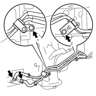
Connect the 2 oil cooler hoses to the oil cooler union sub-assembly and slide the 2 clips to secure them.
Note
Make sure the pinching portion of each clip is facing toward the RH side of the vehicle.
-
Temporarily install the oil cooler tube sub-assembly with the 2 bolts.
-
Tighten the bolts in the order shown in the illustration.
- Torque:
- 22 N*m { 224 kgf*cm, 16 ft.*lbf }
-
-
CONNECT WIRE HARNESS AND CONNECTOR
-
Connect the park/neutral position switch assembly connector.
-
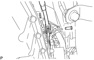
Connect the transmission wire connector.
Tech Tips
Push up the lever until the claw of the transmission wire connector makes a connection sound.
-
Install the wire harness to the automatic transmission assembly with the 5 clamps and nut.
- Torque:
- 10 N*m { 102 kgf*cm, 7 ft.*lbf }
-
-
INSTALL NO. 2 EARTH WIRE
-
Install the No. 2 earth wire to the automatic transmission assembly with the bolt.
- Torque:
- 13 N*m { 133 kgf*cm, 10 ft.*lbf }
-
-
INSTALL REAR ENGINE MOUNTING MEMBER
-
Temporarily install the rear engine mounting member to the rear engine mounting bracket with the 4 nuts.
-
Install the rear engine mounting member to the body with the 4 bolts.
- Torque:
- 34.7 N*m { 354 kgf*cm, 26 ft.*lbf }
-
Fully tighten the 4 nuts to the rear engine mounting bracket.
- Torque:
- 13 N*m { 133 kgf*cm, 10 ft.*lbf }
-
-
INSTALL FLOOR SHIFT GEAR SHIFTING ROD SUB-ASSEMBLY
-
Install the floor shift gear shifting rod sub-assembly to the transmission control shaft lever RH with the pin.
-
Install a new clip.
-
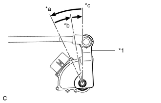
*1 Transmission Control Shaft Lever RH *a P *b R *c N Turn the transmission control shaft lever RH counterclockwise until it stops, then turn it clockwise 2 notches.
-
Move the shift lever to N.
-
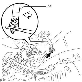
*a Lever 
Pushing the lever rearward Temporarily install the floor shift gear shifting rod sub-assembly to the lever of the transmission floor shift assembly with the nut.
-
Tighten the nut while lightly pushing the lever of the transmission floor shift assembly rearward.
- Torque:
- 12.8 N*m { 131 kgf*cm, 9 ft.*lbf }
Note
Do not push the lever of the transmission floor shift assembly too hard.
-
-
INSTALL DRIVE PLATE AND TORQUE CONVERTER SETTING BOLT
-
Turn the crankshaft to gain access to the installation locations of the 6 drive plate and torque converter assembly setting bolts and install each bolt while holding the crankshaft pulley with SST.
- SST
- 09213-70011 ( 09213-70020 )
- Torque:
- 41 N*m { 418 kgf*cm, 30 ft.*lbf }
Note
First install the black colored bolt, and then the remaining 5 silver colored bolts.
-
-
INSTALL FLYWHEEL HOUSING SIDE COVER
-
Install the flywheel housing side cover to the engine assembly.
Note
Make sure that the flywheel housing side cover is securely installed.
-
-
INSTALL STARTER ASSEMBLY
-
INSTALL PROPELLER WITH CENTER BEARING SHAFT ASSEMBLY
-
INSTALL INTAKE AIR SURGE TANK ASSEMBLY
-
ADD ENGINE COOLANT
-
ADD AUTOMATIC TRANSMISSION FLUID
-
CONNECT CABLE TO NEGATIVE BATTERY TERMINAL
Note
When disconnecting the cable, some systems need to be initialized after the cable is reconnected.
-
INSPECT FOR COOLANT LEAK
-
INSPECT SHIFT LEVER POSITION
-
INSPECT FOR EXHAUST GAS LEAK
-
INSTALL NO. 2 ENGINE UNDER COVER
-
INSTALL FRONT SUSPENSION MEMBER BRACE
-
INSTALL ENGINE UNDER COVER
-
RESET MEMORY