AUTOMATIC TRANSMISSION UNIT(for 2GR) DISASSEMBLY

PROCEDURE
-
FIX AUTOMATIC TRANSMISSION ASSEMBLY
-
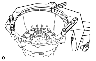
Install the automatic transmission assembly to an overhaul attachment.
-
-
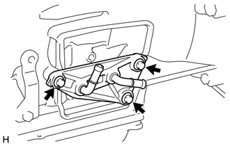
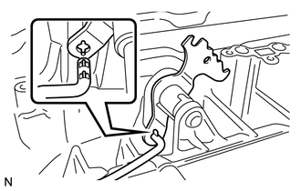
REMOVE WIRE HARNESS CLAMP BRACKET
-
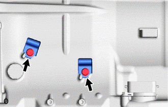
Remove the 2 bolts and the 2 wire harness clamp brackets from the automatic transmission case sub-assembly.
-
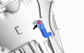
Remove the bolt and the wire harness clamp bracket from the automatic transmission case sub-assembly.
-
-
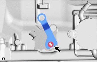
REMOVE TRANSMISSION CONTROL SHAFT LEVER RH
-
Remove the nut, spring washer and the transmission control shaft lever RH from the manual valve lever shaft.
-
-
REMOVE PARK/NEUTRAL POSITION SWITCH ASSEMBLY
-
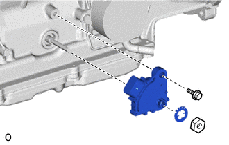
Using a screwdriver, bend the tabs of the lock washer.
-
Remove the nut and the lock washer from the park/neutral position switch assembly.
-
Remove the bolt and the park/neutral position switch assembly from the automatic transmission case sub-assembly.
Tech Tips
Make sure that the manual valve lever shaft has not been rotated prior to installing the park/neutral position switch as the detent spring may become detached from the manual valve lever shaft.
-
-
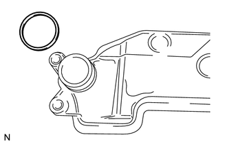
REMOVE TRANSMISSION OIL COOLER (w/ ATF Warmer)
-
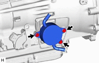
Remove the 3 bolts and transmission oil cooler from the automatic transmission case sub-assembly.
-
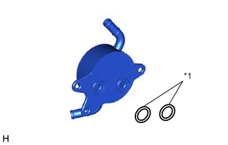
*1 O-ring Remove the 2 O-rings from the transmission oil cooler.
-
-
REMOVE OIL COOLER UNION SUB-ASSEMBLY (w/o ATF Warmer)
-
Remove the 3 bolts and oil cooler union sub-assembly from the automatic transmission case sub-assembly.
-
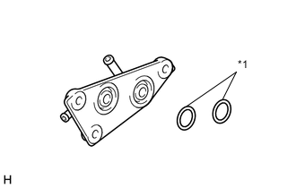
*1 O-ring Remove the 2 O-rings from the oil cooler union sub-assembly.
-
-
REMOVE BREATHER PLUG HOSE
-
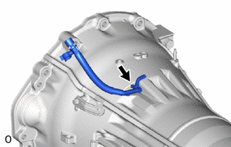
Remove the breather plug hose from the automatic transmission case sub-assembly.
-
Remove the O-ring from the breather plug hose.
-
-
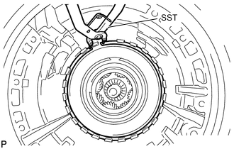
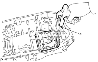
REMOVE AUTOMATIC TRANSMISSION FLANGE YOKE ASSEMBLY
-
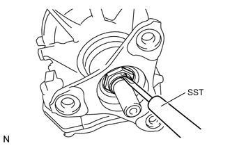
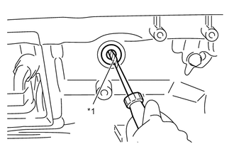
Using SST and a hammer, loosen the staked part of the lock nut.
- SST
- 09930-00010
Note
-
Be sure to use SST with the tapered surface facing the shaft.
-
Do not grind the tip of SST with a grinder or other device.
-
Completely loosen the staked part of the lock nut when removing it
-
Do not damage the threads of the shaft.
-
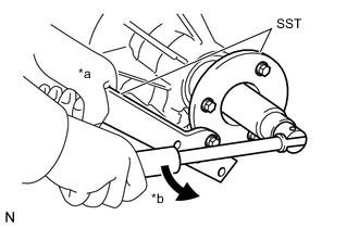
*a Hold *b Turn Using SST and a 30 mm deep socket wrench, remove the lock nut.
- SST
- 09330-00021
- 09950-30012 ( 09955-03040 )
-
Remove SST.
-
Tap the automatic transmission flange yoke assembly with a plastic-faced hammer to remove it.
-
Remove the 2 rear No. 1 output shaft bearing spacers and rear cover sleeve.
-
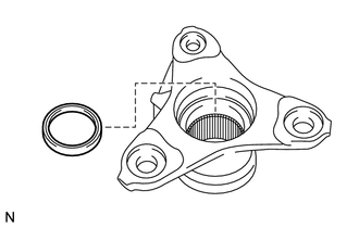
Using a screwdriver, pry out the oil seal from the automatic transmission flange yoke assembly.
Note
Do not damage the automatic transmission flange yoke assembly.
-
-
REMOVE AUTOMATIC TRANSMISSION OIL PAN SUB-ASSEMBLY
Note
Do not turn the transmission over as this will contaminate the transmission valve body assembly with foreign matter located at the bottom of the automatic transmission oil pan sub-assembly.
-
Remove the overflow plug and gasket.
-
Remove the drain plug and gasket.
-
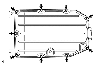
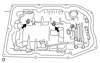
Remove the 9 bolts, automatic transmission oil pan sub-assembly and automatic transmission oil pan gasket.
Note
Do not turn the transmission over as this will contaminate the valve body with foreign matter located at the bottom of the automatic transmission oil pan sub-assembly.
-
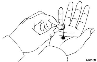
Examine the particles in the pan.
-
Remove the magnets from the oil pan. Use the removed magnets to collect any steel chips. Look carefully at the chips and particles in the pan and on the magnet to anticipate the type of wear which might be found in the transmission.
Result Steel (magnetic) Bearing, gear and clutch plate wear Brass (non-magnetic) Bushing wear
-
-
-
REMOVE VALVE BODY OIL STRAINER ASSEMBLY
-
Turn over the automatic transmission case sub-assembly.
-
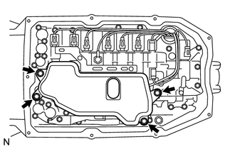
Remove the 4 bolts and valve body oil strainer assembly from the transmission valve body assembly.
-
Remove the O-ring from the valve body oil strainer assembly.
-
-
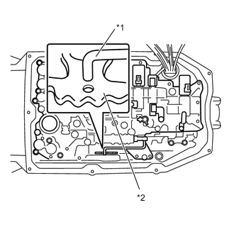
REMOVE TRANSMISSION VALVE BODY ASSEMBLY
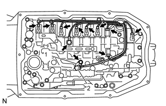
*1 Lock Plate *2 ATF Temperature Sensor
-
Remove the bolt, lock plate and ATF temperature sensor.
-
Remove the O-ring from the ATF temperature sensor.
-
Disconnect the oil pressure switch connector.
-
Disconnect the 9 shift solenoid valve connectors.
-
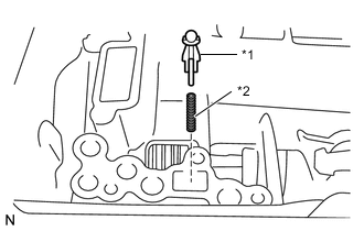
*1 Detent Spring Cover *2 Detent Spring Remove the bolt, detent spring cover and detent spring.
-
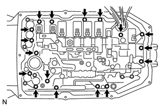
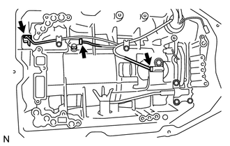
Remove the 17 bolts and transmission valve body assembly.
-
*1 Manual Valve Connecting Rod *2 Manual Valve Lever Sub-assembly Disconnect the manual valve connecting rod from the manual valve lever sub-assembly
-
-
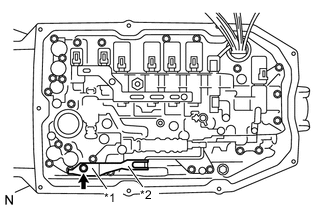
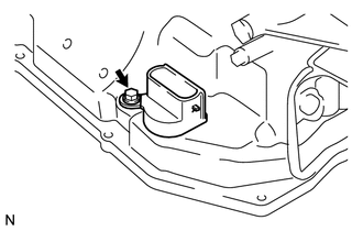
REMOVE CHECK BALL BODY
-
*1 Check Ball Body *2 Spring Remove the check ball body and spring.
-
-
REMOVE TRANSMISSION WIRE
-
Disconnect the 3 connectors from the 3 transmission revolution sensors.
-
Remove the bolt and pull out the transmission wire.
-
Remove the O-ring from the transmission wire connector.
-
Remove the 2 bolts and the 2 valve body wire harness clamps from the automatic transmission case sub-assembly.
-
-
REMOVE TRANSMISSION REVOLUTION SENSOR
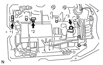
*1 Transmission Revolution Sensor NT *2 Transmission Revolution Sensor NC3 *3 Transmission Revolution Sensor SP2
-
Remove the 2 bolts and 2 transmission revolution sensors NC3 and SP2.
-
Using ''TORX'' socket wrench T30, remove the bolt and transmission revolution sensor NT from the oil pump assembly.
-
Remove the O-ring from the transmission revolution sensor NT.
-
-
REMOVE AUTOMATIC TRANSMISSION CASE PLUG
-
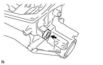
Remove the automatic transmission case plug and O-ring.
-
-
REMOVE PARKING LOCK PAWL BRACKET
-
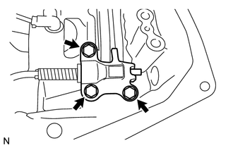
Remove the 3 bolts and parking lock pawl bracket.
-
-
REMOVE PARKING LOCK ROD SUB-ASSEMBLY
-
Disconnect the parking lock rod sub-assembly from the manual valve lever sub-assembly.
-
-
REMOVE PARKING LOCK PAWL SHAFT
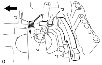
*1 Parking Lock Pawl *2 Parking Lock Pawl Shaft *3 Spring *4 E-ring 
Front Side
-
Pull out the parking lock pawl shaft from the front side, then remove the parking lock pawl and spring.
-
Remove the E-ring from the parking lock pawl shaft.
-
-
REMOVE MANUAL VALVE LEVER SUB-ASSEMBLY
-
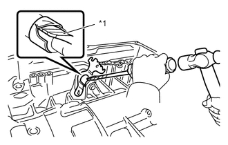
*1 Protective Tape Using a screwdriver and hammer, cut off the spacer and remove it from the manual valve lever shaft.
Note
Be careful not to damage the manual valve lever shaft.
Tech Tips
Wrap the tip of the screwdriver with protective tape.
-
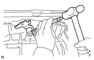
Using a pin punch (3 mm) and hammer, tap out the spring pin.
Tech Tips
Slowly tap out the spring pin so that it does not fall into the automatic transmission case sub-assembly.
-
Pull the manual valve lever shaft out through the automatic transmission case sub-assembly, and remove the manual valve lever sub-assembly.
-
-
REMOVE MANUAL VALVE LEVER SHAFT OIL SEAL
-
*1 Protective Tape Using a screwdriver, pry out the manual valve lever shaft oil seal.
Note
Be careful not to damage the automatic transmission case sub-assembly.
Tech Tips
Wrap the tip of the screwdriver with protective tape.
-
-
REMOVE OIL PUMP ASSEMBLY
-
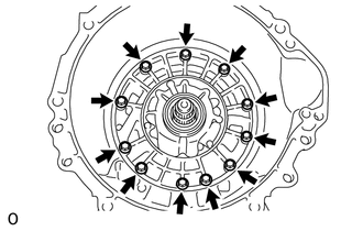
Remove the 11 bolts.
-
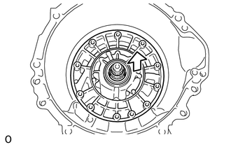
Pull out the oil pump assembly.
Note
Do not damage the oil pump assembly.
-
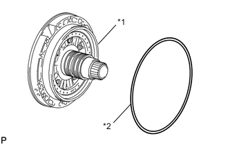
*1 Oil Pump Assembly *2 Oil Pump O-ring Remove the oil pump O-ring from the oil pump assembly.
-
-
REMOVE OVERDRIVE AND REVERSE MULTIPLE DISC CLUTCH ASSEMBLY AND FRONT PLANETARY GEAR ASSEMBLY WITH NO. 1 BRAKE DISC SET
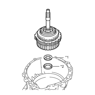
*1 Thrust Needle Roller Bearing *2 Thrust Bearing Race
-
Remove the overdrive and reverse multiple disc clutch assembly and front planetary gear assembly with No. 1 brake disc set from the automatic transmission case sub-assembly.
-
Remove the thrust needle roller bearing and thrust bearing race.
-
-
REMOVE NO. 1 BRAKE DISC
-
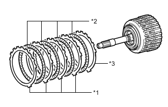
*1 No. 1 Brake Plate *2 No. 1 Brake Disc *3 No. 1 Brake Flange Remove the 4 No. 1 brake plates, 4 No. 1 brake discs and No. 1 brake flange.
-
-
INSPECT NO. 1 BRAKE DISC
-
REMOVE FRONT PLANETARY GEAR ASSEMBLY
-
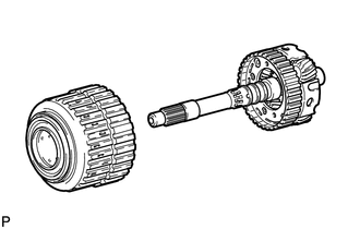
Remove the front planetary gear assembly with the planetary sun gear from the overdrive and reverse multiple disc clutch assembly.
-
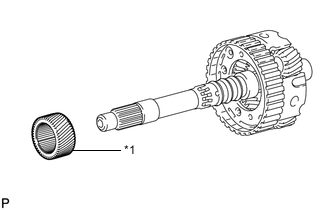
*1 Planetary Sun Gear Remove the planetary sun gear from the front planetary gear assembly.
-
*1 Front Planetary Gear Shaft Snap Ring Remove the 3 front planetary gear shaft snap rings from the front planetary gear assembly.
-
*1 Planetary Carrier Thrust Washer Remove the planetary carrier thrust washer from the front planetary gear assembly.
-
*1 Front Planetary Gear Shaft Snap Ring Remove the 2 front planetary gear shaft snap rings from the front planetary gear assembly.
-
*1 Front Planetary Gear Thrust Needle Roller Bearing Remove the front planetary gear thrust needle roller bearing from the front planetary gear assembly.
-
-
INSPECT FRONT PLANETARY GEAR ASSEMBLY
-
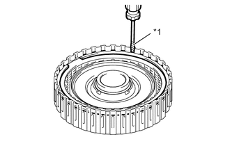
REMOVE NO. 3 CLUTCH DISC
-
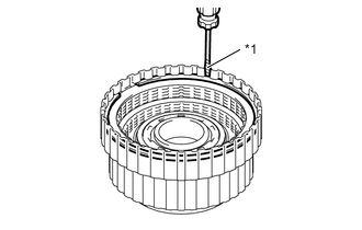
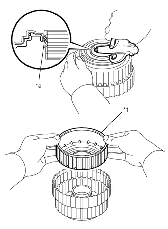
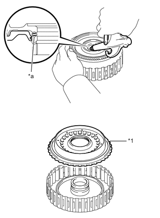
*1 Protective Tape Using a screwdriver, remove the snap ring from the overdrive direct clutch drum sub-assembly.
Note
Be careful not to damage the overdrive direct clutch drum sub-assembly.
Tech Tips
Wrap the tip of the screwdriver with protective tape.
-
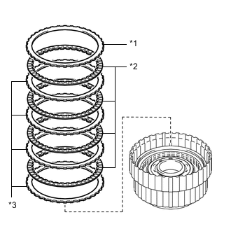
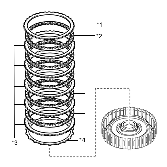
*1 No. 3 Clutch Flange *2 No. 3 Clutch Disc *3 No. 3 Clutch Plate Remove the No. 3 Clutch flange, 4 No. 3 Clutch discs and 4 No. 3 Clutch plates from the overdrive direct clutch drum sub-assembly.
-
-
INSPECT NO. 3 CLUTCH DISC
-
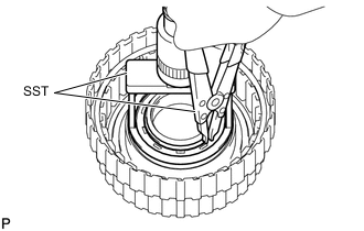
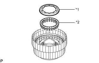
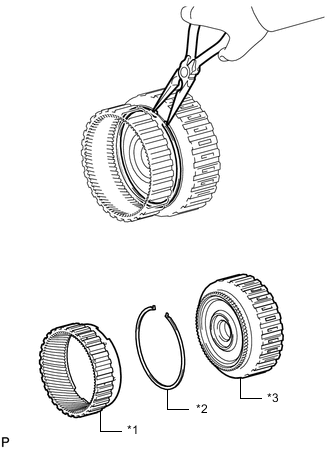
REMOVE REVERSE CLUTCH DISC
-
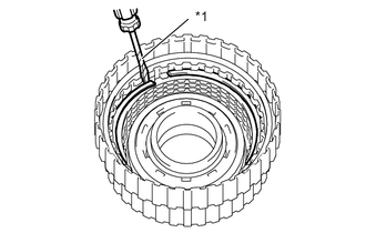
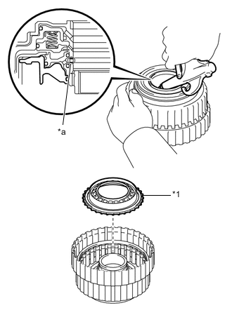
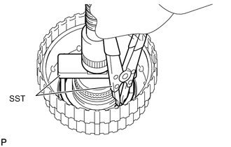
*1 Protective Tape Using a screwdriver, remove the snap ring from the reverse clutch drum sub-assembly.
Note
Be careful not to damage the reverse clutch drum sub-assembly.
Tech Tips
Wrap the tip of the screwdriver with protective tape.
-
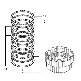
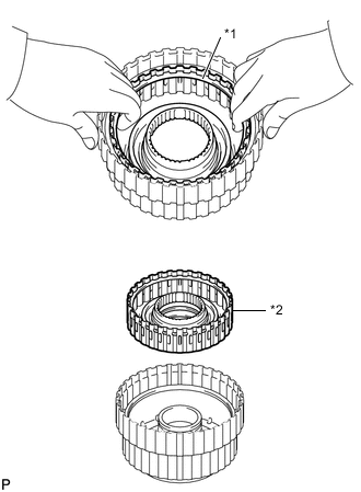
*1 Reveres Clutch Flange *2 Reveres Clutch Disc *3 Reveres Clutch Plate Remove the reveres clutch flange, 5 reveres clutch discs and 5 reveres clutch plates from the reveres clutch drum sub-assembly.
-
-
INSPECT REVERSE CLUTCH DISC
-
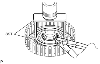
REMOVE REVERSE CLUTCH PISTON
-
Place SST on the reverse clutch balancer, and compress the reveres clutch return spring sub-assembly with a press.
- SST
- 09380-50010 ( 09381-05020 )
-
Using SST, remove the snap ring.
- SST
- 09350-30020 ( 09350-07070 )
-
*1 Reverse Clutch Balancer *2 Reveres Clutch Return Spring Sub-assembly Remove the reverse piston balancer and reverse clutch return spring from the reveres clutch drum sub-assembly.
-
*1 Reveres Clutch Piston *a Oil Hole Hold the reveres clutch piston and apply compressed air to the oil hole of the reveres clutch drum sub-assembly to remove the reveres clutch piston.
-
Remove the O-ring from the reveres clutch piston.
-
-
INSPECT REVERSE CLUTCH RETURN SPRING SUB-ASSEMBLY
-
INSPECT REVERSE CLUTCH DRUM SUB-ASSEMBLY
*1 Snap Ring *2 Reverse Clutch Drum Sub-assembly
-
Remove the reverse clutch drum sub-assembly from the overdrive direct clutch drum sub-assembly.
Tech Tips
The reverse clutch drum sub-assembly is easier to remove if a snap ring is installed. Use the snap ring from the "REMOVE REVERSE CLUTCH DISC" procedure.
-
Remove the 3 O-rings from the reverse clutch drum.
-
-
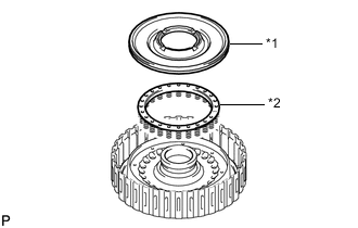
REMOVE OVERDRIVE DIRECT CLUTCH PISTON SUB-ASSEMBLY
-
Place SST on the No. 3 clutch balancer, and compress the overdrive clutch return spring sub-assembly with a press.
- SST
- 09380-50010 ( 09381-05020 )
-
Using SST, remove the snap ring.
- SST
- 09350-30020 ( 09350-07070 )
-
*1 No. 3 Clutch Balancer *2 Overdrive Clutch Return Spring Sub-assembly Remove the No. 3 clutch balancer and overdrive clutch return spring sub-assembly.
-
Remove the O-ring from the No. 3 clutch balancer.
-
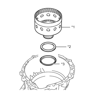
*1 Overdrive Direct Clutch Piston Sub-assembly *a Oil Hole Hold the overdrive direct clutch piston sub-assembly and apply compressed air to the oil hole of the overdrive direct clutch drum sub-assembly to remove the overdrive direct clutch piston sub-assembly.
-
Remove the O-ring from the overdrive direct clutch piston sub-assembly.
-
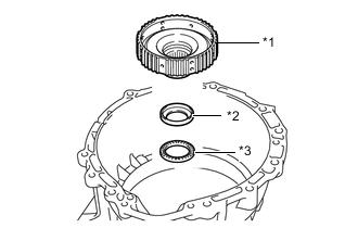
Remove the O-ring from the overdrive direct clutch drum sub-assembly.
-
-
INSPECT OVERDRIVE CLUTCH RETURN SPRING SUB-ASSEMBLY
-
INSPECT OVERDRIVE DIRECT CLUTCH DRUM SUB-ASSEMBLY
-
REMOVE FORWARD MULTIPLE DISC CLUTCH ASSEMBLY WITH FRONT PLANETARY RING GEAR
-
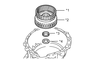
*1 Front Planetary Ring Gear *2 Forward Multiple Disc Clutch assembly *3 Thrust Needle Roller Bearing *4 Thrust Bearing Race Remove the forward multiple disc clutch assembly with front planetary ring gear, thrust needle roller bearing and thrust bearing race from the automatic transmission case sub-assembly.
-
-
REMOVE FRONT PLANETARY RING GEAR
-
*1 Front Planetary Ring Gear *2 Snap Ring *3 Forward Multiple Disc Clutch Assembly Using needle-nose pliers, detach the snap ring and remove the front planetary ring gear and snap ring from the forward multiple disc clutch assembly.
-
-
REMOVE FORWARD MULTIPLE CLUTCH DISC
-
*1 Protective Tape Using a screwdriver, remove the snap ring.
Note
Be careful not to damage the forward multiple disc clutch assembly.
Tech Tips
Wrap the tip of the screwdriver with protective tape.
-
*1 Forward Clutch Flange *2 Forward Multiple Clutch Disc *3 Forward Multiple Clutch Plate *4 Clutch Cushion Plate Remove the forward clutch flange, 5 forward multiple clutch discs, 5 forward multiple clutch plates and clutch cushion plate.
-
-
INSPECT FORWARD MULTIPLE CLUTCH DISC
-
REMOVE FORWARD CLUTCH PISTON
-
Place SST on the No. 1 clutch balancer, and compress the forward clutch return spring sub-assembly with a press.
- SST
- 09380-50010 ( 09381-05020 )
-
Using SST, remove the snap ring.
- SST
- 09350-30020 ( 09350-07070 )
-
*1 No. 1 Clutch Balancer *2 Forward Clutch Return Spring Sub-assembly Remove the No. 1 clutch balancer and forward clutch return spring sub-assembly from the forward clutch drum sub-assembly.
-
Remove the O-ring from the No. 1 clutch balancer.
-
*a Oil Hole *1 Forward Clutch Piston Hold the forward clutch piston and apply compressed air to the oil hole of the forward clutch drum sub-assembly to remove the forward clutch piston.
-
Remove the 2 O-rings from the forward clutch piston.
-
-
INSPECT FORWARD CLUTCH RETURN SPRING SUB-ASSEMBLY
-
INSPECT FORWARD CLUTCH DRUM SUB-ASSEMBLY
-
REMOVE MULTIPLE DISC CLUTCH HUB
-
*1 Multiple Disc Clutch Hub *2 Thrust Bearing Race *3 Thrust Needle Roller Bearing Remove the multiple disc clutch hub from the automatic transmission case sub-assembly.
-
Remove the thrust bearing race and thrust needle roller bearing from the automatic transmission case sub-assembly.
-
-
REMOVE SUN GEAR INPUT DRUM SUB-ASSEMBLY
-
*1 Sun Gear Input Drum Sub-assembly *2 Thrust Needle Roller Bearing *3 Thrust Bearing Race Remove the sun gear input drum sub-assembly, thrust needle roller bearing and thrust bearing race from the automatic transmission case sub-assembly.
-
-
INSPECT SUN GEAR INPUT DRUM SUB-ASSEMBLY
-
REMOVE ONE-WAY CLUTCH OUTER RACE WITH NO. 1 ONE-WAY CLUTCH
-
Using SST, remove the snap ring from the automatic transmission case sub-assembly.
- SST
- 09350-30020 ( 09350-07060 )
-
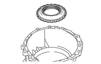
Remove the one-way clutch outer race with No. 1 one-way clutch.
-
-
REMOVE REAR PLANETARY SUN GEAR ASSEMBLY
-
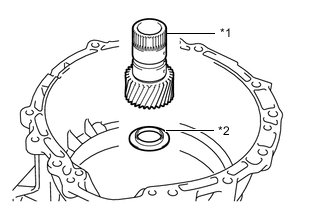
*1 Rear Planetary Sun Gear Assembly *2 Thrust Bearing Race Remove the rear planetary sun gear assembly and thrust bearing race from the automatic transmission case sub-assembly.
-
-
INSPECT REAR PLANETARY SUN GEAR ASSEMBLY
-
REMOVE REAR PLANETARY GEAR ASSEMBLY
-
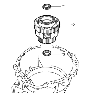
*1 Thrust Needle Roller Bearing *2 Rear Planetary Gear Assembly *3 Thrust Bearing Race Remove the thrust needle roller bearing, rear planetary gear assembly and thrust bearing race from the automatic transmission case sub-assembly.
-
-
INSPECT NO. 1 ONE-WAY CLUTCH
-
REMOVE NO. 1 ONE-WAY CLUTCH
-
*1 Snap Ring *2 No.1 One-way Clutch *3 One-way Clutch Outer Race Remove the 2 snap rings and No. 1 one-way clutch from the one-way clutch outer race.
-
-
INSPECT REAR PLANETARY GEAR ASSEMBLY
-
REMOVE NO. 2 BRAKE DISC
-
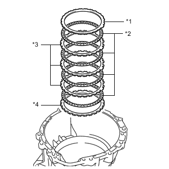
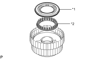
*1 Brake Plate *2 No. 2 Brake Disc *3 No. 2 Brake Plate *4 No. 2 Brake Flange Remove the brake plate, 4 No. 2 brake discs, 3 No. 2 brake plates and No. 2 brake flange.
-
-
INSPECT NO. 2 BRAKE DISC
-
REMOVE DIRECT MULTIPLE DISC CLUTCH ASSEMBLY AND REAR PLANETARY RING GEAR WITH OUTPUT SHAFT SUB-ASSEMBLY
-
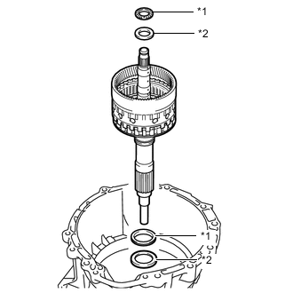
*1 Thrust Needle Roller Bearing *2 Thrust Bearing Race Remove the 2 thrust needle roller bearings, 2 thrust bearing races, direct multiple disc clutch assembly and rear planetary ring gear with output shaft sub-assembly from the automatic transmission case sub-assembly.
-
-
REMOVE REAR PLANETARY RING GEAR
-
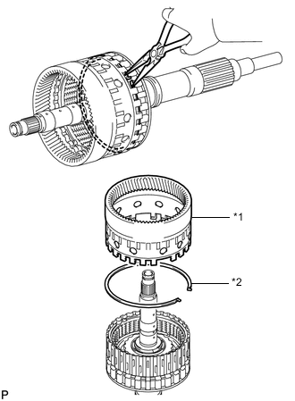
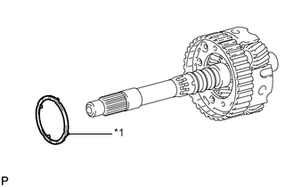
*1 Rear Planetary Ring Gear *2 Snap Ring Using needle-nose pliers, detach the snap ring and remove the rear planetary ring gear from the output shaft sub-assembly.
-
-
REMOVE MULTIPLE DISC CLUTCH ASSEMBLY
-
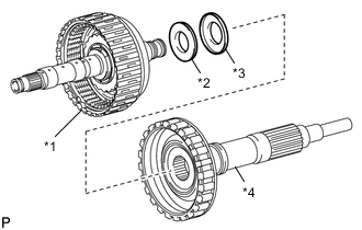
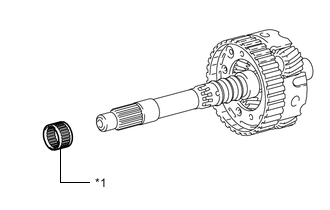
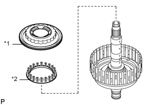
*1 Multiple Disc Clutch Assembly *2 Thrust Needle Roller Bearing *3 Thrust Bearing Race *4 Output Shaft Sub-assembly Remove the multiple disc clutch assembly from the output shaft sub-assembly.
-
Remove the thrust needle roller bearing and thrust bearing race from the output shaft sub-assembly.
-
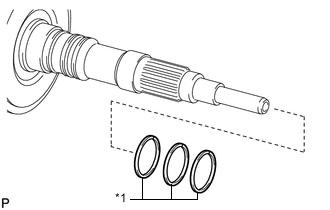
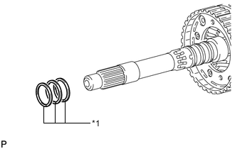
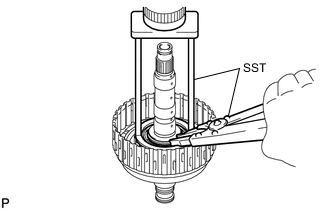
*1 Oil Seal Ring Remove the 3 oil seal rings from the output shaft sub-assembly.
-
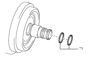
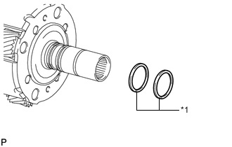
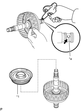
*1 Oil Seal Ring Remove the 2 oil seal rings from the multiple disc clutch assembly.
-
-
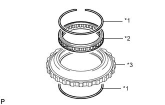
REMOVE NO. 2 CLUTCH DISC
-
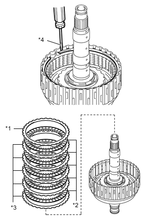
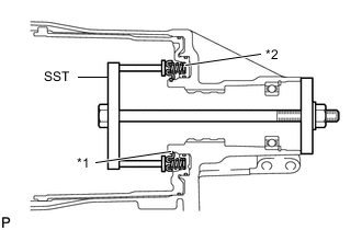
*1 No. 2 Clutch Flange *2 No. 2 Clutch Disc *3 No. 2 Clutch Plate *4 Protective Tape Remove the snap ring and No. 2 clutch flange, 5 No. 2 clutch discs and 5 No. 2 clutch plates from the direct clutch drum sub-assembly.
Note
Be careful not to damage the direct clutch drum sub-assembly.
Tech Tips
Wrap the tip of the screwdriver with protective tape.
-
-
INSPECT NO. 2 CLUTCH DISC
-
REMOVE DIRECT CLUTCH PISTON
-
Place SST on the No. 2 clutch balancer, and compress the direct clutch return spring sub-assembly with a press.
- SST
- 09387-00020
-
Using SST, remove the snap ring.
- SST
- 09350-30020 ( 09350-07070 )
-
*1 No. 2 Clutch Balancer *2 Direct Clutch Return Spring Sub-assembly Remove the No. 2 clutch balancer and direct clutch return spring sub-assembly from the direct clutch drum sub-assembly.
-
Remove the O-ring from the No. 2 clutch balancer.
-
*a Oil Hole *1 Direct Clutch Piston Hold the direct clutch piston and apply compressed air to the oil hole of the direct clutch drum sub-assembly to remove the direct clutch piston.
-
Remove the O-ring from the direct clutch piston.
-
Remove the O-ring from the direct clutch drum sub-assembly.
-
-
INSPECT DIRECT CLUTCH RETURN SPRING SUB-ASSEMBLY
-
REMOVE NO. 2 BRAKE PISTON
-
*1 Snap Ring *2 2nd Brake Piston Return Spring Sub-assembly Set SST on the 2nd brake piston return spring sub-assembly, tighten SST and compress the 2nd brake piston return spring sub-assembly.
- SST
- 09380-50010 ( 09381-05010, 09381-05020 )
-
Using SST, remove the snap ring and the 2nd brake piston return spring sub-assembly.
-
*a Oil Hole Hold the No. 2 brake piston and apply compressed air to the oil hole of the automatic transmission case sub-assembly to remove the No. 2 brake piston.
-
Remove the 3 O-rings from the No. 2 brake piston.
-
-
INSPECT 2ND BRAKE PISTON RETURN SPRING SUB-ASSEMBLY
-
REMOVE BRAKE PLATE STOPPER SPRING
-
Remove the 2 brake plate stopper springs.
-
-
REMOVE AUTOMATIC TRANSMISSION REAR OIL SEAL
-
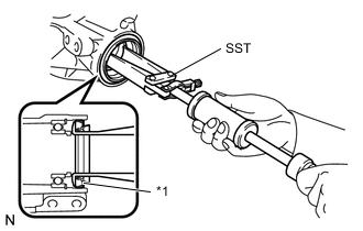
*1 Automatic Transmission Rear Oil Seal Using SST, tap out the automatic transmission rear oil seal.
- SST
- 09308-00010
-
-
REMOVE OUTPUT SHAFT REAR RADIAL BALL BEARING
-
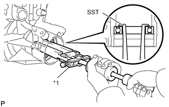
*1 Output Shaft Rear Radial Ball Bearing Using snap ring pliers, remove the snap ring from the automatic transmission case sub-assembly.
-
Using SST, remove the output shaft rear radial ball bearing.
- SST
- 09308-00010
-