VALVE BODY ASSEMBLY(for 2GR) INSTALLATION
PROCEDURE
-
INSTALL TRANSMISSION VALVE BODY ASSEMBLY
-
Install the spring and check ball body.
-
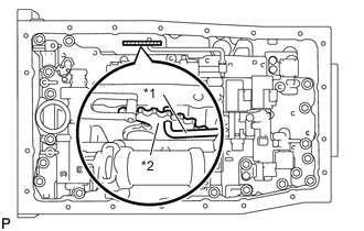
*1 Manual Valve Connecting Rod *2 Manual Valve Lever Sub-assembly Align the groove of the manual valve lever sub-assembly with the manual valve connecting rod.
-
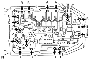
Install the transmission valve body assembly with the 17 bolts.
Tech Tips
Each bolt length is indicated below.
- Torque:
- 11 N*m { 112 kgf*cm, 8 ft.*lbf }
Bolt length Bolt A 21 mm (0.8268 in.) Bolt B 31 mm (1.2205 in.) Bolt C 64 mm (2.5197 in.) -
Install the detent spring and detent spring cover with the bolt.
- Torque:
- 10 N*m { 102 kgf*cm, 7 ft.*lbf }
-
Connect the 9 connectors to the solenoid valves.
-
Connect the oil pressure switch connector.
-
Coat a new O-ring with ATF and install to the ATF temperature sensor.
-
Install the ATF temperature sensor and lock plate with the bolt.
- Torque:
- 10 N*m { 102 kgf*cm, 7 ft.*lbf }
-
-
INSTALL VALVE BODY OIL STRAINER ASSEMBLY
-
Coat a new O-ring with ATF and install it to the valve body oil strainer assembly.
Note
Ensure that the O-ring is not twisted or pinched.
-
Install the valve body oil strainer assembly to the transmission valve body assembly with the 4 bolts.
- Torque:
- 10 N*m { 102 kgf*cm, 7 ft.*lbf }
-
-
INSTALL AUTOMATIC TRANSMISSION OIL PAN SUB-ASSEMBLY
-
Install the 3 transmission oil cleaner magnets to the automatic transmission oil pan sub-assembly.
-
Install a new automatic transmission oil pan gasket and the automatic transmission oil pan sub-assembly to the automatic transmission case sub-assembly with the 9 bolts.
- Torque:
- 7.4 N*m { 75 kgf*cm, 65 in.*lbf }
Note
-
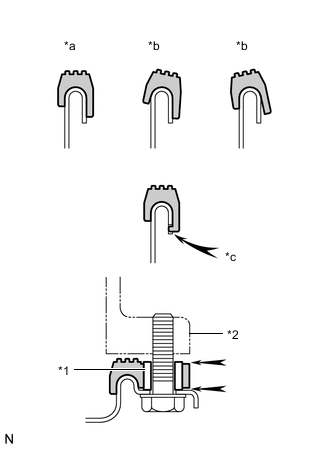
*1 Sleeve *2 Automatic Transmission Case Sub-assembly *a Correct *b Incorrect *c Protrusion Make sure that there is no oil or foreign matter on the gasket seal surface and automatic transmission oil pan sub-assembly contact surface.
-
Install the gasket so that there is no slack in the gasket, and that the seal surface's entire circumference is level.
-
Make sure that the 9 gasket drop prevention protrusions are set on the automatic transmission oil pan sub-assembly.
-
When tightening the automatic transmission oil pan sub-assembly, make sure that the gasket is not pinched between the gasket tightening area's sleeve and the transmission's seal surface.
-
-
INSTALL NO. 1 EXHAUST PIPE SUPPORT BRACKET SUB-ASSEMBLY
-
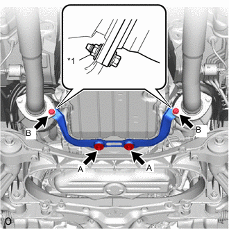
*1 Nut Install the No. 1 exhaust pipe support bracket sub-assembly with the 2 bolts (A), 2 new bolts (B) and 2 new nuts.
Tech Tips
When installing on the exhaust side, hold the nuts while tightening the bolts.
- Torque:
- for Bolt A
- 43 N*m { 438 kgf*cm, 32 ft.*lbf }
- for Bolt B
- 39 N*m { 398 kgf*cm, 29 ft.*lbf }
-
-
INSTALL NO. 2 ENGINE UNDER COVER
-
INSTALL FRONT SUSPENSION MEMBER BRACE
-
ADD AUTOMATIC TRANSMISSION FLUID
-
RESET MEMORY