AUTOMATIC TRANSMISSION SYSTEM(for 2GR-FKS), Diagnostic DTC:P070513, P070562
| DTC Code | DTC Name |
|---|---|
| P070513 | Transmission Range Sensor "A" Circuit Open |
| P070562 | Transmission Range Sensor "A" Signal Compare Failure |
DESCRIPTION
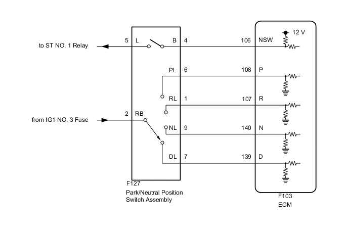
The park/neutral position switch assembly detects the shift lever position and sends signals to the ECM.
| DTC No. | Detection Item | DTC Detection Condition | Trouble Area | MIL | Memory | Note |
|---|---|---|---|---|---|---|
| P070513 | Transmission Range Sensor "A" Circuit Open | When the engine switch is on (IG) and the battery voltage is 8 V or more, NSW, P, R, N and D input signals are all OFF simultaneously for 60 seconds or more (2-trip detection logic). |
|
Comes on | DTC stored | SAE Code: P0705 |
| P070562 | Transmission Range Sensor "A" Signal Compare Failure | When the engine switch is on (IG) and the battery voltage is 8 V or more, 2 or more of the following signals are ON simultaneously for 2 seconds or more (2-trip detection logic).
|
|
Comes on | DTC stored | SAE Code: P0705 |
| Vehicle Condition | |||||
|---|---|---|---|---|---|
| Pattern 1 | Pattern 2 | Pattern 3 | Pattern 4 | ||
| Diagnostic Condition | Engine switch is on (IG) | ○ | ○ | ○ | ○ |
| Battery voltage is 8 V or more | ○ | ○ | ○ | ○ | |
| Malfunction Condition | NSW input signal is ON | ○ | ○ | - | - |
| P input signal is ON | - | - | ○ | ○ | |
| R input signal is ON | - | ○ | - | ○ | |
| N input signal is ON | - | - | - | - | |
| D input signal is ON | ○ | - | ○ | - | |
| Duration | 2 seconds or more | 2 seconds or more | 2 seconds or more | 2 seconds or more | |
| Detection Logic | 2-trip detection logic | 2-trip detection logic | 2-trip detection logic | 2-trip detection logic | |
| Vehicle Condition | ||||
|---|---|---|---|---|
| Pattern 5 | Pattern 6 | Pattern 7 | ||
| Diagnostic Condition | Engine switch is on (IG) | ○ | ○ | ○ |
| Battery voltage is 8 V or more | ○ | ○ | ○ | |
| Malfunction Condition | NSW input signal is ON | - | - | - |
| P input signal is ON | - | - | - | |
| R input signal is ON | - | ○ | ○ | |
| N input signal is ON | ○ | ○ | - | |
| D input signal is ON | ○ | - | ○ | |
| Duration | 2 seconds or more | 2 seconds or more | 2 seconds or more | |
| Detection Logic | 2-trip detection logic | 2-trip detection logic | 2-trip detection logic | |
Tech Tips
DTC P070562 is stored when any of the above detection patterns are met.
MONITOR DESCRIPTION
This DTC indicates a problem with the park/neutral position switch assembly or the wire harness in the park/neutral position switch assembly circuit.
The park/neutral position switch assembly detects the shift lever position and sends signals to the ECM.
For safety, the park/neutral position switch assembly detects the shift lever position so that the engine can be started only when the shift lever is in P or N.
The park/neutral position switch assembly sends a signal to the ECM according to the shift lever position (P, N, R, D or M).
The ECM determines that there is a problem with the switch or related parts if it receives more than 1 position signal simultaneously. The ECM will illuminate the MIL and store the DTC.
CONFIRMATION DRIVING PATTERN
Tech Tips
After repairs have been completed, clear the DTCs and then check that the vehicle has returned to normal by performing the following All Readiness check procedure.
-
Connect the GTS to the DLC3.
-
Turn the engine switch on (IG) and turn the GTS on.
-
Clear the DTCs (even if no DTCs are stored, perform the clear DTC procedure).
-
Turn the engine switch off and wait for 2 minutes or more.
-
Turn the engine switch on (IG) and turn the GTS on.
-
Wait with the shift lever in each position (P, R, N and D) for 60 seconds or more each with the engine switch on (IG).
-
Enter the following menus: Powertrain / Transmission / Utility / All Readiness.
-
Input the DTC: P070513 or P070562.
-
Check the DTC judgment result.
GTS Display Description NORMAL
-
DTC judgment completed
-
System normal
ABNORMAL
-
DTC judgment completed
-
System abnormal
INCOMPLETE
-
DTC judgment not completed
-
Perform driving pattern after confirming DTC enabling conditions
N/A
-
Unable to perform DTC judgment
-
Number of DTCs which do not fulfill DTC preconditions has reached ECU memory limit
Tech Tips
-
If the judgment result shows NORMAL, the system is normal.
-
If the judgment result shows ABNORMAL, the system has a malfunction.
-
If the judgment result shows INCOMPLETE or N/A, perform the Confirmation Driving Pattern and check the DTC judgment result again.
-
WIRING DIAGRAM
CAUTION / NOTICE / HINT
Note
-
Inspect the fuses for circuits related to this system before performing the following procedure.
-
Perform registration and/or initialization when parts related to the automatic transmission are replaced.
PROCEDURE
-
CHECK HARNESS AND CONNECTOR (BATTERY - PARK/NEUTRAL POSITION SWITCH ASSEMBLY)
-
Disconnect the F127 park/neutral position switch assembly connector.
-
Measure the voltage according to the value(s) in the table below.
Standard Voltage Tester Connection Condition Specified Condition F127-2 (RB) - Body ground Engine switch on (IG) 11 to 14 V F127-2 (RB) - Body ground Engine switch off Below 1 V Result Proceed to OK NG
NG 
REPAIR OR REPLACE HARNESS OR CONNECTOR
OK 
-
-
CHECK HARNESS AND CONNECTOR (POWER SOURCE)
-
Disconnect the F127 park/neutral position switch assembly connector.
-
Measure the voltage according to the value(s) in the table below.
Standard Voltage Tester Connection Condition Specified Condition F127-4 (B) - Body ground Engine switch on (IG) 11 to 14 V F127-4 (B) - Body ground Engine switch off Below 1 V Result Proceed to OK NG
NG 
CHECK HARNESS AND CONNECTOR (PARK/NEUTRAL POSITION SWITCH ASSEMBLY - ECM) Click here
OK
-
-
INSPECT PARK/NEUTRAL POSITION SWITCH ASSEMBLY
-
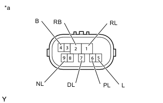
*a Component without harness connected
(Park/Neutral Position Switch Assembly)
Disconnect the F127 park/neutral position switch assembly connector.
-
Measure the resistance according to the value(s) in the table below.
Standard Resistance Tester Connection Condition Specified Condition 4 (B) - 5 (L) Shift lever in P or N Below 1 Ω 2 (RB) - 6 (PL) Shift lever in P Below 1 Ω 2 (RB) - 1 (RL) Shift lever in R Below 1 Ω 2 (RB) - 9 (NL) Shift lever in N Below 1 Ω 2 (RB) - 7 (DL) Shift lever in D, M, "+" or "-" Below 1 Ω 4 (B) - 5 (L) Shift lever not in P or N 10 kΩ or higher 2 (RB) - 6 (PL) Shift lever not in P 10 kΩ or higher 2 (RB) - 1 (RL) Shift lever not in R 10 kΩ or higher 2 (RB) - 9 (NL) Shift lever not in N 10 kΩ or higher 2 (RB) - 7 (DL) Shift lever not in D, M, "+" or "-" 10 kΩ or higher Result Proceed to OK NG
NG
REPLACE PARK/NEUTRAL POSITION SWITCH ASSEMBLY Click here
OK
-
-
CHECK HARNESS AND CONNECTOR (PARK/NEUTRAL POSITION SWITCH ASSEMBLY - ECM)
-
Disconnect the F103 ECM connector.
-
Turn the engine switch on (IG).
-
Measure the voltage according to the value(s) in the table below.
Standard Voltage Tester Connection Condition Specified Condition F103-108 (P) - Body ground
-
Engine switch on (IG)
-
Shift lever in P
11 to 14 V F103-107 (R) - Body ground
-
Engine switch on (IG)
-
Shift lever in R
11 to 14 V* F103-140 (N) - Body ground
-
Engine switch on (IG)
-
Shift lever in N
11 to 14 V F103-139 (D) - Body ground
-
Engine switch on (IG)
-
Shift lever in D, M, "+" or "-"
11 to 14 V F103-108 (P) - Body ground
-
Engine switch on (IG)
-
Shift lever not in P
Below 1 V F103-107 (R) - Body ground
-
Engine switch on (IG)
-
Shift lever not in R
Below 1 V F103-140 (N) - Body ground
-
Engine switch on (IG)
-
Shift lever not in N
Below 1 V F103-139 (D) - Body ground
-
Engine switch on (IG)
-
Shift lever not in D, M, "+" or "-"
Below 1 V Tech Tips
*: The voltage will drop slightly due to the back up light turning on.
Result Proceed to OK NG -
NG
REPAIR OR REPLACE HARNESS OR CONNECTOR
OK
-
-
REPLACE ECM
-
Replace the ECM.
Result Proceed to NEXT
NEXT
PERFORM A/T CODE REGISTRATION Click here
-
-
CHECK HARNESS AND CONNECTOR (PARK/NEUTRAL POSITION SWITCH ASSEMBLY - ECM)
-
Disconnect the F127 park/neutral position switch assembly connector.
-
Disconnect the F103 ECM connector.
-
Measure the resistance according to the value(s) in the table below.
Standard Resistance Tester Connection Condition Specified Condition F127-4 (B) - F103-106 (NSW) Always Below 1 Ω F127-4 (B) or F103-106 (NSW) - Body ground and other terminals Always 10 kΩ or higher Result Proceed to OK NG
NG
REPAIR OR REPLACE HARNESS OR CONNECTOR
OK
-
-
REPLACE ECM
-
Replace the ECM.
Result Proceed to NEXT
NEXT
PERFORM A/T CODE REGISTRATION Click here
-