AUTOMATIC TRANSMISSION SYSTEM(for 2GR-FKS), Diagnostic DTC:P07757F
| DTC Code | DTC Name |
|---|---|
| P07757F | Pressure Control Solenoid "B" Actuator Stuck Off |
DESCRIPTION
Based on signals from the transmission revolution sensors (NT, SP2 and NC3), the actual gear is detected.
If the detected gear is different than the commanded gear, the ECM detects related mechanical problems in the shift solenoid valves, transmission valve body assembly and automatic transmission assembly.
Tech Tips
| ECM commanded gear | 1st | 2nd | 3rd | 4th | 5th | 6th | 7th | 8th |
|---|---|---|---|---|---|---|---|---|
| Actual gear during SL2 stuck ON malfunction | 5th | 8th | 7th | 6th | 5th | 6th | 7th | 8th |
| Actual gear during SL2 stuck OFF malfunction | 1st | 2nd | 3rd | 4th | N (1st)* | N* | N* | N* |
*: Neutral
| DTC No. | Detection Item | DTC Detection Condition | Trouble Area | MIL | Memory | Note |
|---|---|---|---|---|---|---|
| P07757F | Pressure Control Solenoid "B" Actuator Stuck Off | All of the following conditions are met (2-trip detection logic):
|
DTC Detection Condition 1, 2, 3, 4 and 5 (a):
DTC Detection Condition 1, 2, 3, 4 and 5 (b): |
Comes on | DTC stored | SAE Code: P0776 |
| Vehicle Condition | |||||
|---|---|---|---|---|---|
| Pattern 1 | Pattern 2 | Pattern 3 | Pattern 4 | ||
| Diagnostic Condition | Engine coolant temperature is 40°C (104°F) or higher. | ○ | ○ | ○ | ○ |
| ATF temperature is -10°C (14°F) or more. | ○ | ○ | ○ | ○ | |
| The vehicle is driven with the shift lever in D. | ○ | ○ | ○ | ○ | |
| No malfunctions are detected in the shift solenoid valve SL1, SL2, SL3, SL4, SL5 and SR, transmission revolution sensors (NT, NC3 and SP2), oil pressure switch, engine coolant temperature sensor, ATF temperature sensor, knock control sensor, electronic throttle and CAN communication system. | ○ | ○ | ○ | ○ | |
| Malfunction Condition | When gear shifts to 1st are requested by the ECM, actual gear changes to 5th gear. | ○ | - | - | - |
| When gear shifts to 2nd are requested by the ECM, actual gear changes to 8th gear. | - | ○ | - | - | |
| When gear shifts to 4th are requested by the ECM, actual gear changes to 6th gear. | - | - | ○ | - | |
| When gear shifts to 5th are requested by the ECM, the engine speed overruns (neutral status). | - | - | - | ○ | |
| Duration | 2 times | 2 times | 2 times | 0.5 seconds or more | |
| Detection Logic | 2-trip detection logic | 2-trip detection logic | 2-trip detection logic | 2-trip detection logic | |
| Vehicle Condition | ||||
|---|---|---|---|---|
| Pattern 5 | Pattern 6 | Pattern 7 | ||
| Diagnostic Condition | Engine coolant temperature is 40°C (104°F) or higher. | ○ | ○ | ○ |
| ATF temperature is -10°C (14°F) or more. | ○ | ○ | ○ | |
| The vehicle is driven with the shift lever in D. | ○ | ○ | ○ | |
| No malfunctions are detected in the shift solenoid valve SL1, SL2, SL3, SL4, SL5 and SR, transmission revolution sensors (NT, NC3 and SP2), oil pressure switch, engine coolant temperature sensor, ATF temperature sensor, knock control sensor, electronic throttle and CAN communication system. | ○ | ○ | ○ | |
| Malfunction Condition | When gear shifts to 6th are requested by the ECM, the engine speed overruns (neutral status). | ○ | - | - |
| When gear shifts to 7th are requested by the ECM, the engine speed overruns (neutral status). | - | ○ | - | |
| When gear shifts to 8th are requested by the ECM, the engine speed overruns (neutral status). | - | - | ○ | |
| Duration | 0.5 seconds or more | 0.5 seconds or more | 0.5 seconds or more | |
| Detection Logic | 2-trip detection logic | 2-trip detection logic | 2-trip detection logic | |
Tech Tips
This DTC is stored when any of the above detection patterns are met.
MONITOR DESCRIPTION
The ECM commands gear shifts by turning the shift solenoid valves ON and OFF. According to the input shaft revolution (speed), intermediate (counter) shaft revolution (speed) and output shaft revolution (speed), the ECM detects the actual gear (1st, 2nd, 3rd, 4th, 5th, 6th, 7th or 8th gear position). When the gear commanded by the ECM and the actual gear are not the same, the ECM illuminates the MIL and stores a DTC.
CONFIRMATION DRIVING PATTERN
CAUTION:
When performing the confirmation driving pattern, obey all speed limits and traffic laws.
Tech Tips
After repairs have been completed, clear the DTCs and then check that the vehicle has returned to normal by performing the following All Readiness check procedure.
-
Connect the GTS to the DLC3.
-
Turn the engine switch on (IG) and turn the GTS on.
-
Clear the DTCs (even if no DTCs are stored, perform the clear DTC procedure).
-
Turn the engine switch off and wait for 2 minutes or more.
-
Turn the engine switch on (IG) and turn the GTS on.
-
Start the engine.
-
Perform the D Position Shift Test inspection in Road Test.
-
Stop the vehicle.
-
Enter the following menus: Powertrain / Transmission / Utility / All Readiness.
-
Input the DTC: P07757F.
-
Check the DTC judgment result.
GTS Display Description NORMAL
-
DTC judgment completed
-
System normal
ABNORMAL
-
DTC judgment completed
-
System abnormal
INCOMPLETE
-
DTC judgment not completed
-
Perform driving pattern after confirming DTC enabling conditions
N/A
-
Unable to perform DTC judgment
-
Number of DTCs which do not fulfill DTC preconditions has reached ECU memory limit
Tech Tips
-
If the judgment result shows NORMAL, the system is normal.
-
If the judgment result shows ABNORMAL, the system has a malfunction.
-
If the judgment result shows INCOMPLETE or N/A, perform the Confirmation Driving Pattern and check the DTC judgment result again.
-
CAUTION / NOTICE / HINT
Note
Perform registration and/or initialization when parts related to the automatic transmission are replaced.
PROCEDURE
-
CHECK DTC OUTPUT
-
Connect the GTS to the DLC3.
-
Turn the engine switch on (IG).
-
Turn the GTS on.
-
Enter the following menus: Powertrain / Transmission / Trouble Codes.
Powertrain > Transmission > Trouble Codes -
Read the DTCs using the GTS.
Result Result Proceed to Only DTCs P07707F, P07757F and P27137F are output A Only DTC P07757F is output B P07707F, P07757F, P27137F and other DTCs are output C Tech Tips
If any DTCs other than P07707F, P07757F and P27137F are output, perform troubleshooting for those DTCs first.
B 
INSPECT SHIFT SOLENOID VALVE SL2 Click here
C 
GO TO DTC CHART Click here
A 
-
-
CLEAR DTC AND PERFORM STALL SPEED TEST
-
Clear the DTCs.
Powertrain > Transmission > Clear DTCsTech Tips
Write down the currently output DTCs before clearing them.
-
Perform the stall speed test.
Result Result Proceed to Stall speed test can be performed A Stall speed test cannot be performed B
B
INSPECT SHIFT SOLENOID VALVE SLT Click here
A
-
-
CLEAR DTC AND PERFORM RUNNING TEST
-
Clear the DTCs.
Powertrain > Transmission > Clear DTCsTech Tips
Write down the currently output DTCs before clearing them.
-
Start the engine, drive the vehicle and perform the inspection.
Result Result Proceed to
-
Gear cannot be shifted between 1st gear and 4th gear
-
Gear can only be shifted from 4th gear to 5th gear
-
Gear cannot be shifted between 5th gear and 8th gear*
A
-
Gear can be shifted from 1st gear to 4th gear
-
For 5th gear and above, gear shifts to neutral
B Conditions other than those listed above C Tech Tips
*: If the gear is shifted to 5th gear or above, gear shifts will no longer be able to be performed. When performing the test again, first clear the DTCs.
-
B
GO TO STEP 12 Click here
C
CHECK TRANSMISSION REVOLUTION SENSOR TERMINAL (NC3 TERMINAL) Click here
A
-
-
INSPECT SHIFT SOLENOID VALVE SR
-
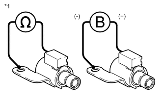
*1 Shift Solenoid Valve SR Remove the shift solenoid valve SR.
-
Measure the resistance according to the value(s) in the table below.
Standard Resistance Tester Connection Condition Specified Condition Terminal of shift solenoid valve SR connector - Shift solenoid valve SR body 20°C (68°F) 11 to 15 Ω -
Connect a positive (+) lead from the battery to the terminal of the shift solenoid valve connector, and a negative (-) lead to the shift solenoid valve body. Check that the valve moves and makes an operating sound.
OK Valve moves and makes an operating sound. Result Proceed to OK NG
NG
REPLACE SHIFT SOLENOID VALVE SR Click here
OK
-
-
INSPECT TRANSMISSION VALVE BODY ASSEMBLY
-
Check the transmission valve body assembly.
OK There is no foreign matter on each valve and they operate smoothly. Result Proceed to OK NG
NG
REPAIR OR REPLACE TRANSMISSION VALVE BODY ASSEMBLY Click here
OK
-
-
INSPECT TORQUE CONVERTER ASSEMBLY
-
Check the torque converter assembly.
OK The torque converter assembly operates normally. Result Proceed to OK NG
OK
REPAIR OR REPLACE AUTOMATIC TRANSMISSION ASSEMBLY Click here
NG
REPLACE TORQUE CONVERTER ASSEMBLY Click here
-
-
CHECK TRANSMISSION REVOLUTION SENSOR TERMINAL (NC3 TERMINAL)
-
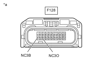
*a Front view of wire harness connector
(to Transmission Wire)
Disconnect the F128 transmission wire connector.
-
Measure the resistance according to the value(s) in the table below.
Standard Resistance Tester Connection Condition Specified Condition F128-12 (NC3O) - Body ground Always 99 to 101 Ω -
Turn the engine switch on (IG).
-
Measure the voltage according to the value(s) in the table below.
Standard Voltage Tester Connection Condition Specified Condition F128-11 (NC3B) - Body ground Engine switch on (IG) 11 to 14 V Result Proceed to OK NG
NG
CHECK HARNESS AND CONNECTOR (TRANSMISSION WIRE - ECM) Click here
OK
-
-
INSPECT TRANSMISSION WIRE (TRANSMISSION REVOLUTION SENSOR (NC3))
-
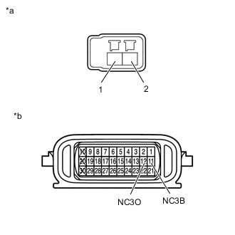
*a Front view of wire harness connector
(to Transmission Revolution Sensor (NC3))
*b Component without harness connected
(Transmission Wire)
Disconnect the transmission revolution sensor (NC3) connector.
-
Disconnect the F128 transmission wire connector.
-
Measure the resistance according to the value(s) in the table below.
Standard Resistance Tester Connection Condition Specified Condition Terminal 1 of the transmission revolution sensor (NC3) connector - 11 (NC3B) Always Below 1 Ω Terminal 2 of the transmission revolution sensor (NC3) connector - 12 (NC3O) Always Below 1 Ω Terminal 1 of the transmission revolution sensor (NC3) connector or 11 (NC3B) - Body ground Always 10 kΩ or higher Terminal 2 of the transmission revolution sensor (NC3) connector or 12 (NC3O) - Body ground Always 10 kΩ or higher Result Proceed to OK NG
OK
REPLACE TRANSMISSION REVOLUTION SENSOR (NC3) Click here
NG
REPAIR OR REPLACE TRANSMISSION WIRE Click here
-
-
CHECK HARNESS AND CONNECTOR (TRANSMISSION WIRE - ECM)
-
Disconnect the F128 transmission wire connector.
-
Disconnect the F103 ECM connector.
-
Measure the resistance according to the value(s) in the table below.
Standard Resistance Tester Connection Condition Specified Condition F128-11 (NC3B) - F103-78 (NC3B) Always Below 1 Ω F128-12 (NC3O) - F103-110 (NC3O) Always Below 1 Ω F128-11 (NC3B) or F103-78 (NC3B) - Body ground Always 10 kΩ or higher F128-12 (NC3O) or F103-110 (NC3O) - Body ground Always 10 kΩ or higher Result Proceed to OK NG
NG
REPAIR OR REPLACE HARNESS OR CONNECTOR
OK
-
-
REPLACE ECM
-
Replace the ECM.
Result Proceed to NEXT
NEXT
PERFORM A/T CODE REGISTRATION Click here
-
-
INSPECT SHIFT SOLENOID VALVE SLT
-

*1 Shift Solenoid Valve SLT Remove the shift solenoid valve SLT.
-
Measure the resistance according to the value(s) in the table below.
Standard Resistance Tester Connection Condition Specified Condition Terminal 1 of the shift solenoid valve SLT - terminal 2 20°C (68°F) 5.0 to 5.6 Ω -
Connect a positive (+) lead from the battery with a 21 W bulb to terminal 1 and a negative (-) lead to terminal 2 of the shift solenoid valve connector. Check that the valve moves and makes an operating sound.
OK Valve moves and makes an operating sound. Result Proceed to OK NG
OK
GO TO STEP 5 Click here
NG
REPLACE SHIFT SOLENOID VALVE SLT Click here
-
-
INSPECT SHIFT SOLENOID VALVE SL2
-
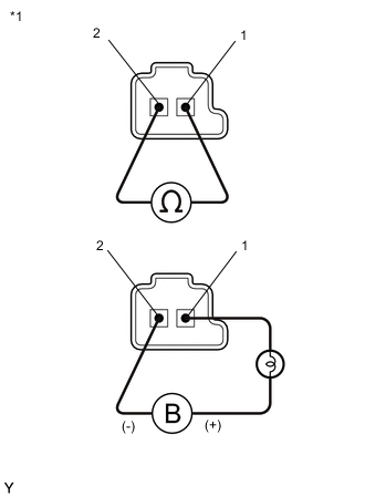
*1 Shift Solenoid Valve SL2 Remove the shift solenoid valve SL2.
-
Measure the resistance according to the value(s) in the table below.
Standard Resistance Tester Connection Condition Specified Condition Terminal 1 of the shift solenoid valve SL2 - terminal 2 20°C (68°F) 5.0 to 5.6 Ω -
Connect a positive (+) lead from the battery with a 21 W bulb to terminal 1 and a negative (-) lead to terminal 2 of the shift solenoid valve connector. Check that the valve moves and makes an operating sound.
OK Valve moves and makes an operating sound. Result Proceed to OK NG
OK
GO TO STEP 5 Click here
NG
REPLACE SHIFT SOLENOID VALVE SL2 Click here
-