AUTOMATIC TRANSMISSION SYSTEM(for 2GR-FKS) DIAGNOSIS SYSTEM
-
EURO-OBD (EUROPEAN SPEC)
-
When troubleshooting Europe On-Board Diagnostic (Euro-OBD) vehicles, an OBD scan tool (complying with ISO 15765-4) must be connected to the vehicle. Various data output from the vehicle's ECM can then be read.
-

Euro-OBD regulations require that the vehicle on-board computer illuminate the Malfunction Indicator Lamp (MIL) on the instrument panel when the computer detects a malfunction in:
-
The emission control system/components
-
The powertrain control components (which affect vehicle emissions)
-
The computer
In addition, the applicable Diagnostic Trouble Codes (DTCs) prescribed by ISO 15765-4 are recorded in the ECM memory.
If the malfunction does not recur in 3 consecutive trips, the MIL turns off automatically but the DTCs remain recorded in the ECM memory.
-
-
To check for DTCs, connect the GTS or an OBD scan tool to the Data Link Connector 3 (DLC3) of the vehicle. The scan tool displays DTCs, freeze frame data and a variety of engine data.
The DTCs and freeze frame data can be cleared with the scan tool.
-
-
M-OBD (except EUROPEAN SPEC)
-
When troubleshooting Multiplex On-Board Diagnostic (M-OBD) vehicles, the GTS must be connected to the vehicle. Various data output from the ECM can then be read.
-
OBD regulations require that the vehicle on-board computer illuminate the Malfunction Indicator Lamp (MIL) on the instrument panel when the computer detects a malfunction in:
-
The emission control system/components
-
The powertrain control components (which affect vehicle emissions)
-
The computer
In addition, the applicable Diagnostic Trouble Codes (DTCs) prescribed by ISO 15765-4 are recorded in the ECM memory.
If the malfunction does not recur in 3 consecutive trips, the MIL turns off automatically but the DTCs remain recorded in the ECM memory.
-
-
To check for DTCs, connect the GTS to the Data Link Connector 3 (DLC3) of the vehicle. The GTS displays DTCs, freeze frame data and a variety of engine data.
The DTCs and freeze frame data can be cleared with the GTS.
-
-
NORMAL MODE AND CHECK MODE
-
The diagnosis system operates in "normal mode" during normal vehicle use. In normal mode, "2-trip detection logic" is used to ensure accurate detection of malfunctions. "Check mode" is also available to technicians as an option. In check mode, "1-trip detection logic" is used for simulating malfunction symptoms and increasing the system's ability to detect malfunctions, including intermittent problems (GTS only).
-
-
2 TRIP DETECTION LOGIC
-
When a malfunction is first detected, the malfunction is temporarily stored in the ECM memory (1st trip). If the same malfunction is detected during the next driving cycle, the MIL is illuminated (2nd trip).
-
-
FREEZE FRAME DATA
-
The ECM records vehicle and driving condition information as freeze frame data the moment a DTC is stored. When troubleshooting, freeze frame data can be helpful in determining whether the vehicle was running or stopped, whether the engine was warmed up or not, whether the air/fuel ratio was lean or rich, as well as other data recorded at the time of a malfunction.
-
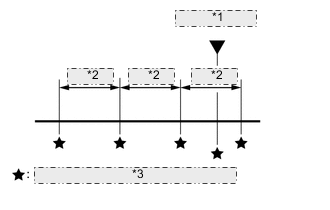
*1 DTC was stored *2 0.5 sec. *3 Freeze frame data which can be read The GTS records freeze frame data in 5 different instances: 1) 3 times before the DTC is stored, 2) once when the DTC is stored, and 3) once after the DTC is stored. These sets of data can be used to simulate the vehicle condition around the time when the malfunction occurred. The data may help in finding the cause of the malfunction, or in judging if the DTC was caused by a temporary malfunction.
-
-
CHECK DATA LINK CONNECTOR 3 (DLC3)
-
Check the DLC3.
-
-
CHECK BATTERY VOLTAGE
If the voltage is below 11 V, recharge or replace the battery.
-
CHECK MIL
-
Check that the MIL illuminates when the engine switch is turned on (IG).
If the MIL does not illuminate, there is a problem in the MIL circuit.
-
When the engine is started, the MIL should turn off.
-