OIL PUMP INSTALLATION
PROCEDURE
-
INSTALL TIMING CHAIN COVER ASSEMBLY
-
Install a new gasket to the cylinder head sub-assembly.
-
Apply a light coat of engine oil to a new No. 2 oil strainer gasket and a new oil pump gasket.
-
Install the No. 2 oil strainer gasket and oil pump gasket to the stiffening crankcase assembly.
-
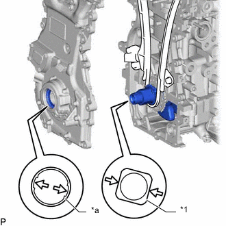
*1 Crankshaft Timing Gear or Sprocket *a Drive Rotor Spline Align the positions of the drive rotor spline and crankshaft timing gear or sprocket as shown in the illustration.
-
Apply seal packing to the timing chain cover assembly at the points shown in the illustration.
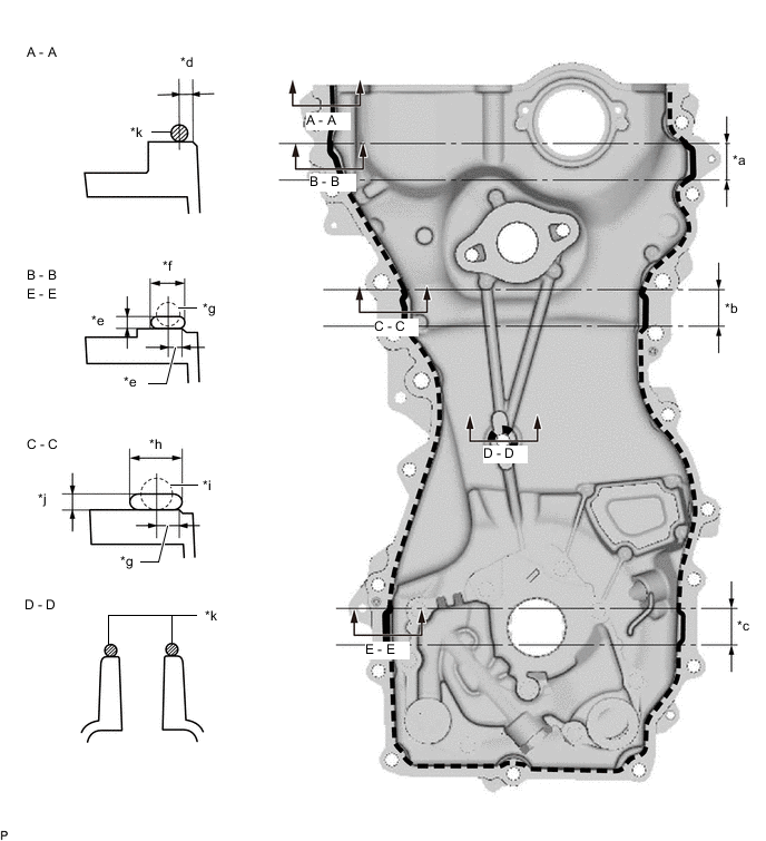
*a 28 mm (1.10 in.) *b 25 mm (0.984 in.) *c 26 mm (1.02 in.) *d 2.5 mm (0.0984 in.) *e 3.0 mm (0.118 in.) *f 7.0 mm (0.276 in.) or more *g 5.0 mm (0.197 in.) *h 13 mm (0.512 in.) or more *i 7.0 mm (0.276 in.) *j 3.0 mm (0.118 in.) or more *k 2.5 to 3.5 mm (0.0984 to 0.138 in.) - - Seal packing Toyota Genuine Seal Packing Black, Three Bond 1207B or equivalent. Seal Packing Application Specification Line Type and Area Seal Packing Diameter Application Area Seal Packing Application Length Coating Width Dashed Line 3.0 mm (0.118 in.) 2.5 mm (0.0984 in.) - - A - A 2.5 to 3.5 mm (0.0984 to 0.138 in.) 2.5 mm (0.0984 in.) - - B - B 5.0 mm (0.197 in.) 3.0 mm (0.118 in.) 28 mm (1.10 in.) Width 7.0 mm (0.276 in.) or more
Thickness 3.0 mm (0.118 in.) or more
C - C 7.0 mm (0.276 in.) 5.0 mm (0.197 in.) 25 mm (0.984 in.) Width 13 mm (0.512 in.) or more
Thickness 3.0 mm (0.118 in.) or more
D - D 2.5 to 3.5 mm (0.0984 to 0.138 in.) - - - E - E 5.0 mm (0.197 in.) - 26 mm (1.02 in.) - Note
-
Using non-residue solvent, clean and remove any oil from the installation surface.
-
Install the part within 3 minutes and tighten the bolts within 10 minutes after applying seal packing.
-
Do not add engine oil for at least 2 hours after installation.
-
Do not start the engine within 2 hours after installation.
-
-
Temporarily install the timing chain cover assembly with the 3 nuts and 19 bolts.
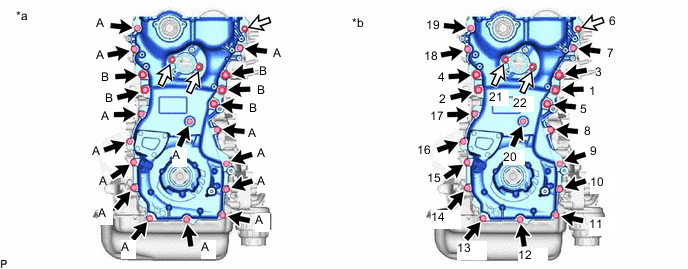
*a Types of nuts and bolts *b Tightening Order 
Bolt 
Nut Bolt Length Item Length Thread Diameter Bolt A 30 mm (1.18 in.) 8 mm (0.315 in.) Bolt B 35 mm (1.38 in.) 10 mm (0.394 in.) Note
-
Do not apply oil to bolts. Clean off if any oil is applied to bolts.
-
When tightening the 15th bolt shown in the illustration, be careful not to damage the installation surface of the crankshaft position sensor.
-
-
Tighten the 19 bolts and 3 nuts in several steps, in the sequence shown in the illustration.
- Torque:
- Bolt A, Nut
- 21 N*m { 214 kgf*cm, 15 ft.*lbf }
- Bolt B
- 55 N*m { 561 kgf*cm, 41 ft.*lbf }
-
-
INSTALL TIMING GEAR CASE OR TIMING CHAIN CASE OIL SEAL
-
INSTALL CRANKSHAFT PULLEY ASSEMBLY
-
INSTALL CRANK POSITION SENSOR
-
INSTALL V-RIBBED BELT TENSIONER ASSEMBLY
-
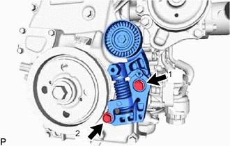
Install the V-ribbed belt tensioner assembly with the 2 bolts in the order shown in the illustration.
- Torque:
- 21 N*m { 214 kgf*cm, 15 ft.*lbf }
-
-
INSTALL IDLER PULLEY SUB-ASSEMBLY
-
Install the idler pulley sub-assembly to the timing chain cover assembly with the bolt.
- Torque:
- 43 N*m { 438 kgf*cm, 32 ft.*lbf }
-
-
INSTALL CAM TIMING OIL CONTROL SOLENOID ASSEMBLY
-
INSTALL AIR CLEANER BRACKET
-
Install the air cleaner bracket to the timing chain cover assembly with the bolt.
- Torque:
- 10 N*m { 102 kgf*cm, 7 ft.*lbf }
-
-
INSTALL OIL LEVEL DIPSTICK GUIDE
-
Apply a light coat of engine oil to a new O-ring.
-
Install the O-ring to the oil level dipstick guide.
-
Install the oil level dipstick guide to the timing chain cover assembly with the bolt.
- Torque:
- 10 N*m { 102 kgf*cm, 7 ft.*lbf }
-
-
INSTALL OIL LEVEL DIPSTICK SUB-ASSEMBLY
-
Install the oil level dipstick sub-assembly.
-
-
INSTALL WATER OUTLET SUB-ASSEMBLY
-
Install a new O-ring to the timing chain cover assembly.
-
Install the water outlet sub-assembly to the timing chain cover assembly with the 2 bolts and nut.
- Torque:
- 10 N*m { 102 kgf*cm, 7 ft.*lbf }
-
-
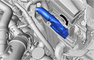
INSTALL NO. 6 WATER BY-PASS HOSE
-
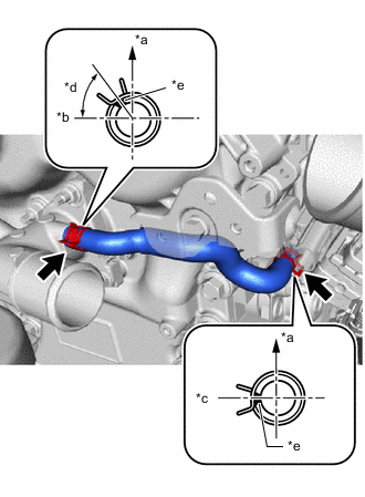
*a Upper Side *b Front Side *c LH Side *d 45° *e Paint Mark Connect the No. 6 water by-pass hose with the 2 clips as shown in the illustration.
Tech Tips
Install the clips so that they are positioned as shown in the illustration.
-
-
INSTALL CAMSHAFT BEARING CAP OIL HOLE GASKET
-
INSTALL CYLINDER HEAD COVER GASKET
-
INSTALL CYLINDER HEAD COVER SUB-ASSEMBLY
-
CONNECT NO. 3 VENTILATION HOSE
-
INSTALL NO. 1 TURBO WATER PIPE
-
CONNECT ENGINE WIRE
-
for Engine Upper Side:
-
Connect the engine wire to the cylinder head cover sub-assembly with the bolt.
- Torque:
- 10 N*m { 102 kgf*cm, 7 ft.*lbf }
-
Attach the clamp and connect the No. 3 ventilation hose to the engine wire.
-
Connect the 2 connectors to the 2 camshaft position sensors.
-
Connect the connector to the air fuel ratio sensor.
-
-
for Engine Front Side:
-
Connect the engine wire to the timing chain cover assembly with the bolt and 3 nuts.
- Torque:
- 10 N*m { 102 kgf*cm, 7 ft.*lbf }
-
Attach the clamp and connect the 5 connectors.
-
-
for Engine LH Side:
-
Attach the clamp and connect the connector.
-
Connect the connector and engine wire with the 2 bolts.
- Torque:
- 21 N*m { 214 kgf*cm, 15 ft.*lbf }
-
-
Attach the claw to connect the connector holder to the engine room ECU box.
-
Attach the wire harness clamp and connect the engine wire with the nut.
- Torque:
- 10 N*m { 102 kgf*cm, 7 ft.*lbf }
-
Connect the connector to the ECM and lock with the lever.
Note
-
When connecting a connector, make sure that dirt, water and other foreign matter is not stuck between the connector and ECM.
-
Make sure that the lever is securely lowered.
-
-
Connect the 4 connectors.
-
-
INSTALL ENGINE ROOM ECU COVER
-
CONNECT SUCTION HOSE
-
Remove the vinyl tape from the suction hose.
-
Sufficiently apply compressor oil to a new O-ring and the fitting surface of the suction hose.
Compressor Oil for HFC-134a(R134a) ND-OIL 8 or equivalent for HFO-1234yf(R1234yf) ND-OIL 12 or equivalent Note
The oil used for HFC-134a (R134a) systems (ND-OIL 8) does not work well in HFO-1234yf (R1234yf) systems. If the oil used for HFC-134a (R134a) systems (ND-OIL 8) is used in HFO-1234yf (R1234yf) system, it will result in degradation of the refrigerant and deterioration of resin parts.
-
Install the O-ring to the suction hose.
Note
Keep the O-ring and O-ring fitting surface free of foreign matter.
-
Connect the suction hose to the suction pipe sub-assembly with the nut.
- Torque:
- 9.8 N*m { 100 kgf*cm, 87 in.*lbf }
-
-
INSTALL IGNITION COIL ASSEMBLY
-
INSTALL NO. 4 VENTILATION HOSE
-
CONNECT VENTILATION HOSE
-
INSTALL COOLER COMPRESSOR ASSEMBLY
-
INSTALL FUEL PUMP ASSEMBLY (for High Pressure)
-
INSTALL RADIATOR ASSEMBLY