OIL PUMP REMOVAL
CAUTION / NOTICE / HINT
Note
Do not remove the oil pump and oil pump relief valve from the timing chain cover assembly.
PROCEDURE
-
REMOVE RADIATOR ASSEMBLY
-
REMOVE FUEL PUMP ASSEMBLY (for High Pressure)
-
REMOVE COOLER COMPRESSOR ASSEMBLY
-
REMOVE VENTILATION HOSE
-
REMOVE NO. 4 VENTILATION HOSE
-
REMOVE IGNITION COIL ASSEMBLY
-
REMOVE CAMSHAFT POSITION SENSOR (for Exhaust Side)
-
REMOVE CAMSHAFT POSITION SENSOR (for Intake Side)
-
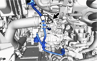
DISCONNECT SUCTION HOSE
-
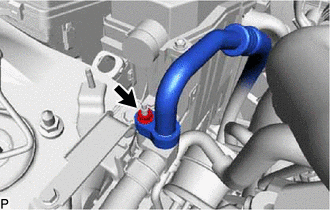
Remove the nut and disconnect the suction hose from the suction pipe sub-assembly.
-
Remove the O-ring from the suction hose.
Note
Seal the openings of the disconnected parts using vinyl tape to prevent moisture and foreign matter from entering them.
-
-
REMOVE ENGINE ROOM ECU COVER
-
DISCONNECT ENGINE WIRE
-
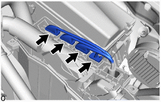
Disconnect the 4 connectors.
-
Disengage the lock, pull up the lever and disconnect the connector of the engine wire from the ECM.
Note
After disconnecting the connector, make sure that dirt, water or other foreign matter does not contact the connecting parts of the connector.
-
Detach the wire harness clamp, remove the nut and disconnect the engine wire.
-
Using a small screwdriver, detach the claw and disconnect the connector holder from the engine room ECU box.
-
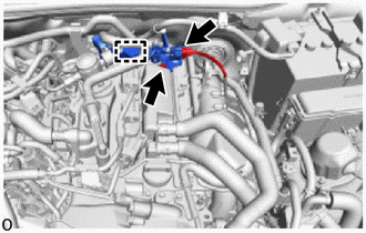
for Engine LH Side:
-
Detach the clamp and disconnect the connector.
-
Remove the 2 bolts and disconnect the connector.
-
-

Bolt 
Nut 
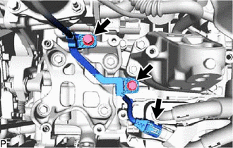
Connector for Engine Front Side:
-
Remove the bolt and 3 nuts.
-
Detach the clamp and disconnect the 5 connectors.
-
-
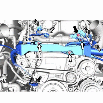
for Engine Upper Side:
-
Detach the clamp and disconnect the No. 3 ventilation hose from the engine wire.
-
Disconnect the air fuel ratio sensor connector.
-
Remove the bolt and disconnect the engine wire from the cylinder head cover sub-assembly.
-
-
-
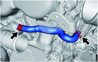
REMOVE NO. 1 TURBO WATER PIPE
-
DISCONNECT NO. 3 VENTILATION HOSE
-
REMOVE CYLINDER HEAD COVER SUB-ASSEMBLY
-
REMOVE CYLINDER HEAD COVER GASKET
-
REMOVE CAMSHAFT BEARING CAP OIL HOLE GASKET
-
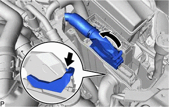
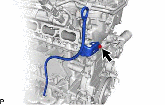
REMOVE NO. 6 WATER BY-PASS HOSE
-
Slide the 2 clips and remove the No. 6 water by-pass hose.
-
-
REMOVE OIL LEVEL DIPSTICK SUB-ASSEMBLY
-
Remove the oil level dipstick sub-assembly.
-
-
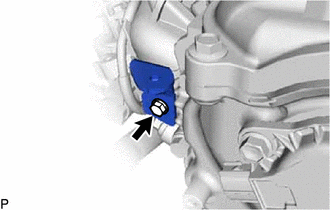
REMOVE OIL LEVEL DIPSTICK GUIDE
-
Remove the bolt and oil level dipstick guide from the timing chain cover assembly.
-
Remove the O-ring from the oil level dipstick guide.
-
-
REMOVE AIR CLEANER BRACKET
-
Remove the bolt and air cleaner bracket from the timing chain cover assembly.
-
-
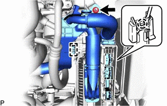
REMOVE WATER OUTLET SUB-ASSEMBLY
-
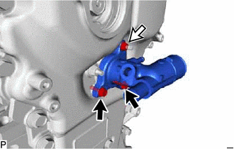
Bolt Nut Remove the 2 bolts, nut and water outlet sub-assembly from the timing chain cover assembly.
-
Remove the O-ring from the timing chain cover assembly.
-
-
REMOVE CAM TIMING OIL CONTROL SOLENOID ASSEMBLY
-
REMOVE IDLER PULLEY SUB-ASSEMBLY
-
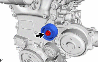
Remove the bolt and idler pulley sub-assembly from the timing chain cover assembly.
-
-
REMOVE V-RIBBED BELT TENSIONER ASSEMBLY
-
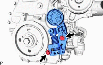
Remove the 2 bolts and V-ribbed belt tensioner assembly from the timing chain cover assembly.
-
-
REMOVE CRANK POSITION SENSOR
-
REMOVE CRANKSHAFT PULLEY ASSEMBLY
-
REMOVE TIMING CHAIN COVER ASSEMBLY
-
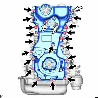
Bolt Nut Remove the 3 nuts and 19 bolts.
-
Using a screwdriver wrapped in protective tape, remove the timing chain cover assembly by prying the points shown in the illustration.
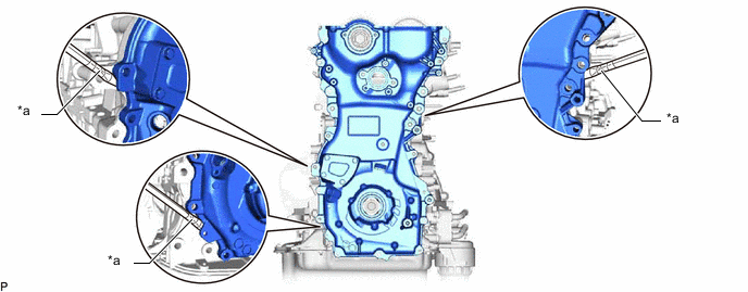
*a Protective Tape - - Note
Do not damage the contacting surfaces of the timing chain cover assembly, camshaft housing sub-assembly, cylinder head sub-assembly, stiffening crankcase assembly and cylinder block sub-assembly.
-
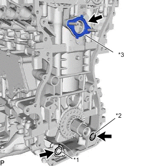
*1 No. 2 Oil Strainer Gasket *2 Oil Pump Gasket *3 Gasket Remove the No. 2 oil strainer gasket and oil pump gasket from the stiffening crankcase assembly.
-
Remove the gasket from the cylinder head sub-assembly.
-
-
REMOVE TIMING GEAR CASE OR TIMING CHAIN CASE OIL SEAL
-
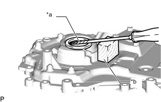
*a Protective Tape *b Wooden Block Using a screwdriver and wooden block, pray out the timing gear case or timing chain case oil seal.
Note
Do not damage the surface of the timing gear case or timing chain case oil seal press fit hole.
-