THERMOSTAT INSPECTION
PROCEDURE
-
INSPECT WATER INLET WITH THERMOSTAT SUB-ASSEMBLY
-
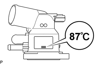
Check the valve opening.
Tech Tips
The valve opening temperature is inscribed on the water inlet with thermostat sub-assembly.
-
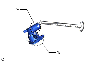
*a Inlet Pipe Side *b Valve Side Add 15 cc (0.9 cu. in.) of water to the water inlet with thermostat sub-assembly from the inlet pipe side.
-
Confirm that water does not flow out from the valve side of the water inlet with thermostat sub-assembly.
If water flows out from the valve side of the water inlet with thermostat sub-assembly, replace the water inlet with thermostat sub-assembly with a new one.
-
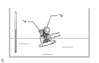
*a Connector *b Inlet Pipe 
Temperature Sensor Immerse the water inlet with thermostat sub-assembly in water that is between 92°C (198°F) and 96°C (205°F) for 5 minutes or more.
Note
-
Do not allow any water to come into contact with the connector of the water inlet with thermostat sub-assembly.
-
Make sure that the end of the inlet pipe of the water inlet with thermostat sub-assembly is not facing downward.
-
Make sure to immerse the water inlet with thermostat sub-assembly in the water as shown in the illustration.
-
-
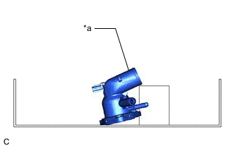
*a Inlet Pipe Leave the water inlet with thermostat sub-assembly at ambient temperature for 5 minutes so that the valve closes.
Note
Make sure that the end of the inlet pipe of the water inlet with thermostat sub-assembly is not facing downward.
-
Check that the water that was added to the water inlet with thermostat sub-assembly has completely flowed out.
If the water that was added to the water inlet with thermostat sub-assembly has not completely flowed out, replace the thermostat sub-assembly with a new one.
-
-
Check the resistance of the temperature sensor.
-
Measure the resistance according to the value(s) in the table below.
Standard Resistance Tester Connection Condition Specified Condition 1 - 2 Always 10.6 to 14.2 Ω If the result is not as specified, replace the water inlet with thermostat sub-assembly.
-
-