INTAKE MANIFOLD INSTALLATION

PROCEDURE
-
INSTALL INTAKE MANIFOLD
-
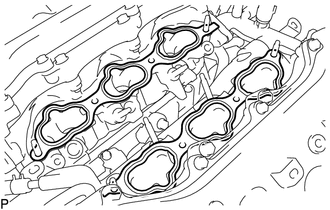
Install 2 new No. 1 intake manifold to head gaskets to each cylinder head sub-assembly as shown in the illustration.
Note
-
Align the port holes of the No. 1 intake manifold to head gaskets and cylinder head sub-assembly.
-
Make sure that the No. 1 intake manifold to head gaskets are installed in the correct direction.
-
-
Temporarily install the intake manifold to the cylinder head sub-assembly with the 4 bolts and 4 nuts.
-
Uniformly tighten the 4 bolts and 4 nuts.
- Torque:
- 21 N*m { 214 kgf*cm, 15 ft.*lbf }
-
-
INSTALL FUEL DELIVERY PIPE WITH SENSOR ASSEMBLY
-
CONNECT WIRE HARNESS
-
INSTALL NO. 1 FUEL TUBE SUB-ASSEMBLY
-
INSTALL NO. 1 ENGINE COVER SUB-ASSEMBLY
-
INSTALL NO. 2 FUEL TUBE SUB-ASSEMBLY
-
INSTALL INTAKE AIR SURGE TANK ASSEMBLY
Note
Do not apply oil to the bolts listed below.
Oil Application Prohibited Bolt Bolt for Intake Air Surge Tank Assembly and Intake Manifold
-
for LHD:
-
Install the No. 1 hose to hose tube to the intake air surge tank assembly with the 2 bolts.
- Torque:
- 9.0 N*m { 92 kgf*cm, 80 in.*lbf }
-
-
Install a new air surge tank to intake manifold gasket to the intake air surge tank assembly.
-
Set the intake air surge tank assembly on the intake manifold.
-
Using an E8 "TORX" socket wrench, install the 2 stud bolts to the intake manifold.
- Torque:
- 10 N*m { 102 kgf*cm, 7 ft.*lbf }
-
Install and uniformly tighten the 5 bolts and 2 nuts.
- Torque:
- 21 N*m { 214 kgf*cm, 15 ft.*lbf }
-
Connect the No. 2 surge tank stay to the intake air surge tank assembly with the bolt.
- Torque:
- 21 N*m { 214 kgf*cm, 15 ft.*lbf }
-
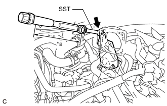
*1 Torque Wrench Fulcrum Length Using SST, connect the No. 2 water by-pass pipe to the intake air surge tank assembly with the bolt.
- SST
- 09290-41010
- Torque:
- Specified tightening torque
- 21 N*m { 214 kgf*cm, 15 ft.*lbf }
Tech Tips
-
Calculate the torque wrench reading when changing the fulcrum length of the torque wrench.
-
When using SST (fulcrum length of 69 mm (2.72 in.)) + torque wrench (fulcrum length of 162 mm (6.38 in.)):
14.7 N*m (150 kgf*cm, 11 ft.*lbf)
-
Engage the clamp to connect the No. 2 fuel tube sub-assembly.
-
Connect the 6 wire harness clamps to the intake air surge tank assembly.
-
for RHD:
-
Connect the wire harness clamp bracket with the bolt.
- Torque:
- 10 N*m { 102 kgf*cm, 7 ft.*lbf }
-
-
Engage the 2 clamps to connect the No. 2 water by-pass hose to the intake air surge tank assembly.
-
Connect the ventilation hose assembly to the intake air surge tank assembly and slide the clip to secure it.
-
Connect the purge valve (purge VSV) to the intake air surge tank assembly with the bolt.
- Torque:
- 21 N*m { 214 kgf*cm, 15 ft.*lbf }
-
Connect the No. 1 fuel vapor feed hose to the intake air surge tank assembly.
-
Connect the purge valve (purge VSV) connector.
-
-
CONNECT VACUUM HOSE ASSEMBLY (for LHD)
-
Connect the union to check valve hose to the vacuum pump assembly and slide the clip to secure it.
-
Connect the vacuum hose assembly to the No. 1 hose to hose tube and slide the clip to secure it.
-
-
INSTALL COWL TOP VENTILATOR LOUVER SUB-ASSEMBLY
-
INSTALL THROTTLE BODY WITH MOTOR ASSEMBLY
-
CONNECT CABLE TO NEGATIVE BATTERY TERMINAL
Note
When disconnecting the cable, some systems need to be initialized after the cable is reconnected.
-
INSPECT FOR FUEL LEAK