INTAKE MANIFOLD REMOVAL

PROCEDURE
-
DISCHARGE FUEL SYSTEM PRESSURE
-
PRECAUTION
Note
After turning the engine switch off, waiting time may be required before disconnecting the cable from the negative (-) battery terminal. Therefore, make sure to read the disconnecting the cable from the negative (-) battery terminal notices before proceeding with work.
-
DISCONNECT CABLE FROM NEGATIVE BATTERY TERMINAL
Note
When disconnecting the cable, some systems need to be initialized after the cable is reconnected.
-
REMOVE THROTTLE BODY WITH MOTOR ASSEMBLY
-
REMOVE COWL TOP VENTILATOR LOUVER SUB-ASSEMBLY
-
DISCONNECT VACUUM HOSE ASSEMBLY (for LHD)
-
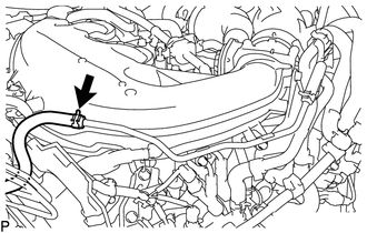
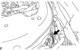
Slide the clip and disconnect the vacuum hose assembly from the No. 1 hose to hose tube.
-
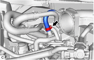
Slide the clip and disconnect the union to check valve hose from the vacuum pump assembly.
-
-
REMOVE INTAKE AIR SURGE TANK ASSEMBLY
-
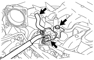
Disconnect the purge valve (purge VSV) connector.
-
Disconnect the No. 1 fuel vapor feed hose from the intake air surge tank assembly.
-
Remove the bolt and disconnect the purge valve (purge VSV) from the intake air surge tank assembly.
-
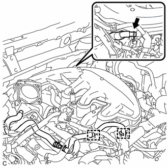
Slide the clip and disconnect the ventilation hose assembly from the intake air surge tank assembly.
-
Disengage the 2 clamps to disconnect the No. 2 water by-pass hose from the intake air surge tank assembly.
-
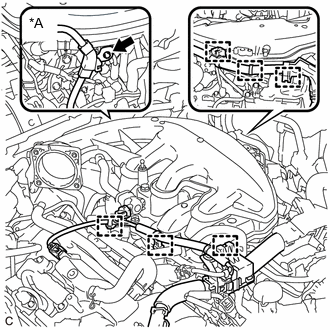
*A for RHD Disconnect the 6 wire harness clamps from the intake air surge tank assembly.
-
for RHD:
-
Remove the bolt and disconnect the wire harness clamp bracket.
-
-
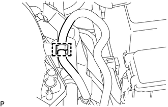
Disengage the clamp to disconnect the No. 2 fuel tube sub-assembly.
-

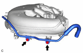
Remove the bolt and disconnect the No. 2 water by-pass pipe from the intake air surge tank assembly.
-
Remove the bolt and disconnect the No. 2 surge tank stay from the intake air surge tank assembly.
-
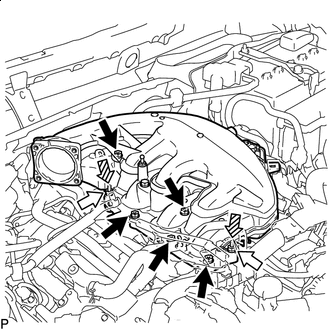

Bolt 
Nut 
Stud Bolt Remove the 2 nuts.
-
Using an E8 "TORX" socket wrench, remove the 2 stud bolts from the intake manifold.
-
Remove the 5 bolts and intake air surge tank assembly.
-
Remove the air surge tank to intake manifold gasket from the intake air surge tank assembly.
-
for LHD:
-
Remove the 2 bolts and No. 1 hose to hose tube from the intake air surge tank assembly.
-
-
-
REMOVE NO. 2 FUEL TUBE SUB-ASSEMBLY
-
REMOVE NO. 1 ENGINE COVER SUB-ASSEMBLY
-
REMOVE NO. 1 FUEL TUBE SUB-ASSEMBLY
-
DISCONNECT WIRE HARNESS
-
REMOVE FUEL DELIVERY PIPE WITH SENSOR ASSEMBLY
-
REMOVE INTAKE MANIFOLD
-
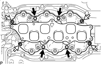
Bolt Nut Remove the 4 bolts, 4 nuts and intake manifold from the cylinder head sub-assembly.
-
Remove the 2 No. 1 intake manifold to head gaskets from each cylinder head sub-assembly.
-