EXHAUST PIPE INSTALLATION

PROCEDURE
-
INSTALL TAIL EXHAUST PIPE BAFFLE SUB-ASSEMBLY
-
Set 2 new tail exhaust pipe baffle sub-assemblies to the tail exhaust pipe assembly and tail exhaust pipe LH.
-
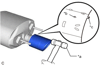
*a Plastic Hammer *b Protrusion *c Cutout Align the cutout of each tail exhaust pipe baffle sub-assembly with the protrusion of the tail exhaust pipe assembly and tail exhaust pipe LH as shown in the illustration.
-
Using a plastic hammer, uniformly tap each tail exhaust pipe baffle sub-assembly onto the tail exhaust pipe assembly and tail exhaust pipe LH.
-
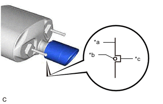
*a Tail Exhaust Pipe Baffle Sub-assembly Edge *b Protrusion *c Cutout Check that the cutout of each tail exhaust pipe baffle sub-assembly is aligned with the protrusion on the bottom of the tail exhaust pipe assembly and tail exhaust pipe LH as shown in the illustration.
Tech Tips
Adjust the tail exhaust pipe baffle sub-assemblies if necessary.
-
-
CONNECT TAIL EXHAUST PIPE LH
-
Connect the tail exhaust pipe LH to the 3 exhaust pipe supports.
-
-
CONNECT TAIL EXHAUST PIPE ASSEMBLY
-
Connect the tail exhaust pipe assembly to the 3 exhaust pipe supports.
-
-
INSTALL FRONT EXHAUST PIPE ASSEMBLY (TWC: Rear Catalyst)
-
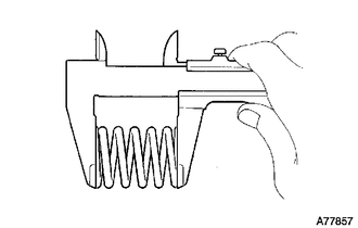
Using a vernier caliper, measure the free length of the compression springs.
Standard length 40 mm (1.57 in.) Minimum free length 38.5 mm (1.52 in.) If the free length is less than the minimum, replace the compression spring.
-
Temporarily install 2 new gaskets to the front exhaust pipe assembly (TWC: Rear Catalyst) for tail exhaust pipe assembly and tail exhaust pipe LH side.
-
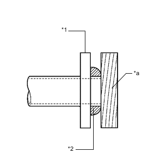
*1 Front Exhaust Pipe Assembly (TWC: Rear Catalyst) *2 Gasket *a Wooden Block Using a plastic hammer and wooden block, tap in each gasket until its surface is flush with the front exhaust pipe assembly (TWC: Rear Catalyst).
Note
-
Be sure to install the gaskets in the correct direction.
-
Do not reuse the gaskets.
-
Do not damage the gaskets.
-
Do not push in the gaskets by using the front exhaust pipe assembly (TWC: Rear Catalyst) when connecting it.
-
-
Install 2 new gaskets to the front exhaust pipe assembly (TWC: Rear Catalyst) for exhaust manifold sub-assembly LH (TWC: Front Catalyst) and exhaust manifold sub-assembly RH (TWC: Front Catalyst) side.
-
Connect the front exhaust pipe assembly (TWC: Rear Catalyst) with 4 new nuts and 4 new bolts.
- Torque:
- 39 N*m { 398 kgf*cm, 29 ft.*lbf }
-
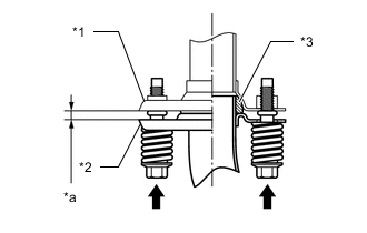
*1 Tail Exhaust Pipe Assembly and Tail Exhaust Pipe LH *2 Front Exhaust Pipe Assembly (TWC: Rear Catalyst) *3 Gasket *a Space between flanges: 6.5 mm (0.256 in.) Install the front exhaust pipe assembly (TWC: Rear Catalyst) to the tail exhaust pipe assembly and tail exhaust pipe LH with the 4 bolts and 4 compression springs.
- Torque:
- 43 N*m { 438 kgf*cm, 32 ft.*lbf }
Tech Tips
After installation, check that the space between the flanges of the front exhaust pipe assembly (TWC: Front Catalyst) and tail exhaust pipe assembly and tail exhaust pipe LH are consistent front-to-rear and left-to-right.
-
-
CONNECT HEATED OXYGEN SENSOR
-
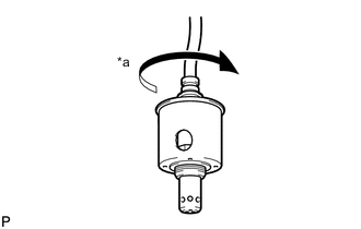
*a 4 Turns Before installing the heated oxygen sensor, twist the sensor wire counterclockwise 4 turns.
-
for Bank 2:
-
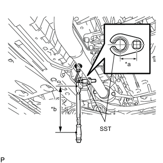
*a Length of SST 30 mm (1.18 in.) *b Length of Torque Wrench 260 mm (10.2 in.) Using SST, install the heated oxygen sensor to the front exhaust pipe assembly (TWC: Rear Catalyst).
- SST
- 09224-00010
- Torque:
- without SST [Torque (N*m (kgf*cm, ft.*lbf))]
- 44 N*m { 449 kgf*cm, 32 ft.*lbf }
- with SST [Reading of Torque wrench (N*m (kgf*cm, ft.*lbf))]
- 39 N*m { 398 kgf*cm, 29 ft.*lbf }
Note
-
Make sure SST and the wrench are connected in a straight line.
-
If a heated oxygen sensor has been struck or dropped, replace it.
Tech Tips
-
This torque value is effective when SST is parallel to the torque wrench.
-
The "with SST" torque value is effective when using SST with a fulcrum length of 30 mm (1.18 in.).
-
The "with SST" torque value is effective when using a torque wrench with a fulcrum length of 260 mm (10.2 in.).
-
If using a torque wrench with a different length, or connecting the torque wrench and SST at an angle, refer to the alternate torque values.
-
Connect the heated oxygen sensor grommet to the body.
-
-
for Bank 1:
-
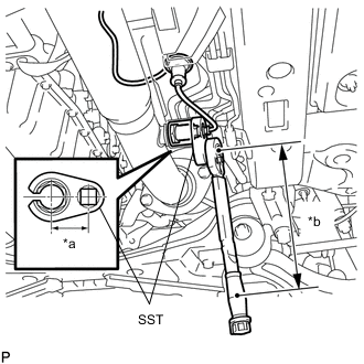
*a Length of SST 30 mm (1.18 in.) *b Length of Torque Wrench 260 mm (10.2 in.) Using SST, install the heated oxygen sensor to the front exhaust pipe assembly.
- SST
- 09224-00010
- Torque:
- without SST [Torque (N*m (kgf*cm, ft.*lbf))]
- 44 N*m { 449 kgf*cm, 32 ft.*lbf }
- with SST [Reading of Torque wrench (N*m (kgf*cm, ft.*lbf))]
- 39 N*m { 398 kgf*cm, 29 ft.*lbf }
Note
-
Make sure SST and the wrench are connected in a straight line.
-
If a heated oxygen sensor has been struck or dropped, replace it.
Tech Tips
-
This torque value is effective when SST is parallel to the torque wrench.
-
The "with SST" torque value is effective when using SST with a fulcrum length of 30 mm (1.18 in.).
-
The "with SST" torque value is effective when using a torque wrench with a fulcrum length of 260 mm (10.2 in.).
-
If using a torque wrench with a different length, or connecting the torque wrench and SST at an angle, refer to the alternate torque values.
-
Connect the heated oxygen sensor grommet to the body.
-
-
-
INSTALL FRONT CENTER FLOOR BRACE
-
Engage the 2 clips.
-
Install the front center floor brace to the body with the 6 bolts and 2 nuts.
- Torque:
- 19 N*m { 194 kgf*cm, 14 ft.*lbf }
-
-
INSTALL REAR NO. 2 FLOOR BOARD SUB-ASSEMBLY (for Full Cover Type)
-
INSTALL REAR NO. 1 FLOOR BOARD SUB-ASSEMBLY (for Full Cover Type)
-
INSPECT FOR EXHAUST GAS LEAK
If gas is leaking, tighten the areas necessary to stop the leak. Replace damaged parts as necessary.
-
Perform "Inspection After Repair" after repairing and replacing an exhaust gas leak.
-