EXHAUST MANIFOLD INSTALLATION
PROCEDURE
-
INSTALL EXHAUST MANIFOLD SUB-ASSEMBLY LH (TWC: Front Catalyst)
-
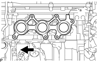
*a Protrusion 
Front Set a new gasket to the cylinder head sub-assembly.
Tech Tips
Orient the protrusion of the gasket as shown in the illustration.
-
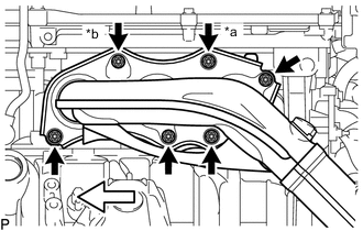
*a Nut A *b Nut B 
Front Temporarily install the exhaust manifold sub-assembly LH (TWC: Front Catalyst) with 6 new nuts.
-
Using a 12 mm deep socket wrench, tighten the 6 nuts.
- Torque:
- 21 N*m { 214 kgf*cm, 15 ft.*lbf }
Note
-
Be sure to tighten either the nut (A) or (B) shown in the illustration first.
-
Do not damage the stud bolts when installing the exhaust manifold sub-assembly LH (TWC: Front Catalyst).
-
-
INSTALL EXHAUST MANIFOLD SUB-ASSEMBLY RH (TWC: Front Catalyst)
-
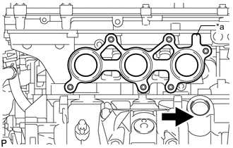
*a Protrusion Front Set a new gasket to the cylinder head sub-assembly.
Tech Tips
Orient the protrusion of the gasket as shown in the illustration.
-
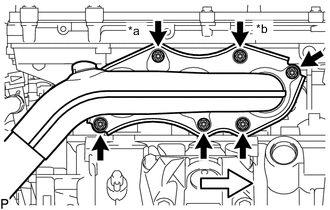
*a Nut A *b Nut B Front Temporarily install the exhaust manifold sub-assembly RH (TWC: Front Catalyst) with 6 new nuts.
-
Using a 12 mm deep socket wrench, tighten the 6 nuts.
- Torque:
- 21 N*m { 214 kgf*cm, 15 ft.*lbf }
Note
-
Be sure to tighten either the nut (A) or (B) shown in the illustration first.
-
Do not damage the stud bolts when installing the exhaust manifold sub-assembly RH (TWC: Front Catalyst).
-
-
INSTALL NO. 2 ENGINE OIL LEVEL DIPSTICK GUIDE
-
Install a new O-ring to the No. 2 engine oil level dipstick guide.
Tech Tips
Apply a light coat of engine oil to the O-ring.
-
Install the No. 2 engine oil level dipstick guide to the cylinder block with the bolt.
- Torque:
- 21 N*m { 214 kgf*cm, 15 ft.*lbf }
-
Install the engine oil level dipstick.
-
-
INSTALL NO. 1 EXHAUST PIPE SUPPORT BRACKET SUB-ASSEMBLY
-
Install the No. 1 exhaust pipe support bracket sub-assembly to the automatic transmission with transfer assembly with the 2 bolts.
- Torque:
- 43 N*m { 438 kgf*cm, 32 ft.*lbf }
-
-
INSTALL FRONT EXHAUST PIPE ASSEMBLY (TWC: Rear Catalyst)
-
CONNECT HEATED OXYGEN SENSOR
-
INSTALL FRONT CENTER FLOOR BRACE
-
INSTALL REAR NO. 2 FLOOR BOARD SUB-ASSEMBLY (for Full Cover Type)
-
INSTALL REAR NO. 1 FLOOR BOARD SUB-ASSEMBLY (for Full Cover Type)
-
INSTALL NO. 2 ENGINE UNDER COVER (for Full Cover Type)
-
INSTALL FRONT SUSPENSION MEMBER BRACE
-
INSTALL AIR FUEL RATIO SENSOR
-
CONNECT NO. 1 ENGINE ROOM RELAY BLOCK AND NO. 1 JUNCTION BLOCK ASSEMBLY (for RHD)
-
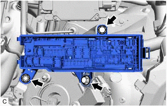
Connect the No. 1 engine room relay block and No. 1 junction block assembly to the body with the 2 bolts and nut.
- Torque:
- 8.0 N*m { 82 kgf*cm, 71 in.*lbf }
-
Connect the wire harness clamp to the body.
-
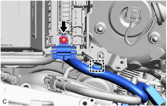
Connect the No. 4 engine wire holder to the No. 1 engine room relay block and No. 1 junction block assembly with the nut.
- Torque:
- 10.5 N*m { 107 kgf*cm, 8 ft.*lbf }
-
Install the No. 1 engine room relay block and No. 1 junction block assembly cover.
-
-
CONNECT CABLE TO NEGATIVE BATTERY TERMINAL (for RHD)
Note
When disconnecting the cable, some systems need to be initialized after the cable is reconnected.
-
INSPECT FOR EXHAUST GAS LEAK