INTAKE MANIFOLD REMOVAL
PROCEDURE
-
DISCHARGE FUEL SYSTEM PRESSURE
-
PRECAUTION
Note
After turning the engine switch off, waiting time may be required before disconnecting the cable from the negative (-) battery terminal. Therefore, make sure to read the disconnecting the cable from the negative (-) battery terminal notice before proceeding with work.
-
DISCONNECT CABLE FROM NEGATIVE BATTERY TERMINAL (w/o Canister Pump Module)
Note
When disconnecting the cable, some systems need to be initialized after the cable is reconnected.
-
REMOVE THROTTLE BODY WITH MOTOR ASSEMBLY
-
REMOVE COWL TOP VENTILATOR LOUVER SUB-ASSEMBLY
-
REMOVE INTAKE AIR SURGE TANK ASSEMBLY
-
w/ Cold Start Fuel Injector Assembly:
-
Disconnect the cold start fuel injector assembly connector.
-
Remove the 2 bolts and separate the cold start fuel injector assembly from the intake air surge tank assembly.
-
Remove the gasket from the intale air surge tank assembly.
-
-
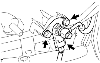
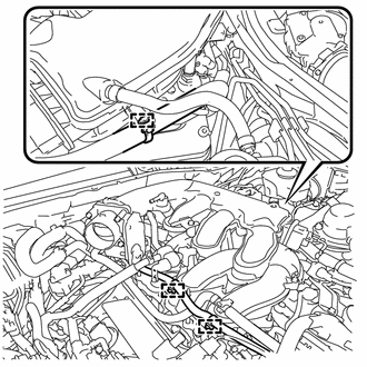
Disconnect the No. 1 fuel vapor feed hose from the purge valve (purge VSV).
-
Disconnect the purge valve (purge VSV) connector.
-
Remove the bolt and purge valve (purge VSV) from the intake air surge tank assembly.
-
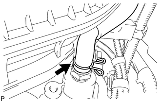
Slide the clip and disconnect the ventilation hose from the PCV valve (ventilation valve sub-assembly).
-
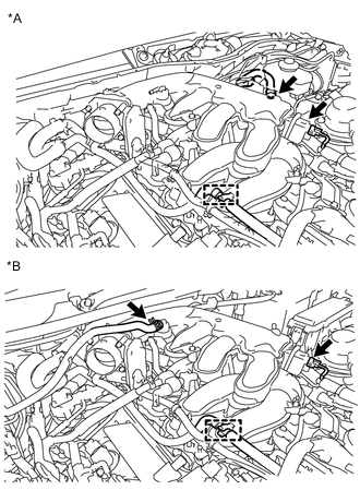
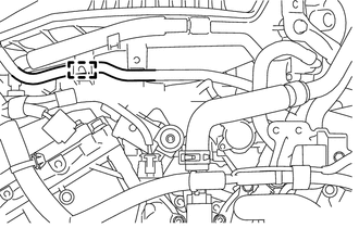
*A for LHD *B for RHD Slide the clip and disconnect the union to check valve hose from the intake air surge tank assembly.
-
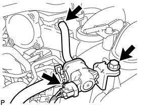
Disconnect the intake air control valve (ACIS) connector.
-
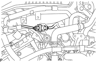
Disconnect the No. 2 water by-pass hose from the intake air surge tank assembly clamp.
-
for LHD:
Disconnect the 3 wire harness clamps from the intake air surge tank assembly.
-
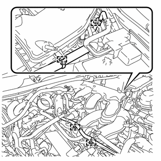
for RHD:
Disconnect the 4 wire harness clamps from the intake air surge tank assembly.
-
Remove the bolt and separate the No. 3 water by-pass pipe from the intake air surge tank assembly.
-
Remove the bolt and separate the No. 2 surge tank stay from the intake air surge tank assembly.
-
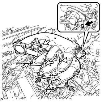

Bolt A 
Bolt B 
Nut Remove the bolt (A) from the intake air surge tank assembly.
-
Remove the 2 nuts from the intake air surge tank assembly.
-
Using a 5 mm long socket hexagon wrench, remove the 6 bolts (B) from the intake air surge tank assembly.
-
w/ Swirl Control Valve Position Sensor:
-
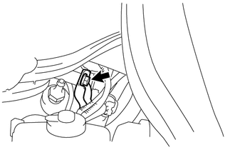
Disconnect the wire harness clamp from the intake air surge tank assembly.
-
-
w/ Cold Start Fuel Injector:
-
Separate the fuel tube sub-assembly clamp from the intake air surge tank assembly.
-
-
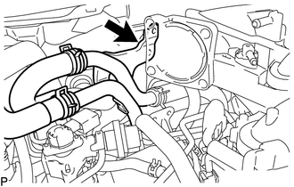
Remove the intake air surge tank assembly and 3 gaskets.
-
-
REMOVE INTAKE MANIFOLD
-
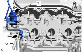
*1 Intake Air Control Valve Actuator (for SCV) *2 Swirl Control Valve Position Sensor (w/ Swirl Control Valve Position Sensor) w/ Swirl Control Valve Position Sensor:
Disconnect the swirl control valve position sensor connector.
-
Disconnect the intake air control valve actuator (for SCV) connector.
-
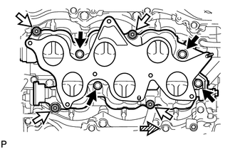
Bolt Nut Front Remove the 4 bolts, 4 nuts and intake manifold from the cylinder head sub-assembly.
-
Remove the 2 gaskets from the cylinder head sub-assembly.
-
-
REMOVE STUD BOLT
Tech Tips
If a stud bolt is deformed or its threads are damaged, replace it.
-
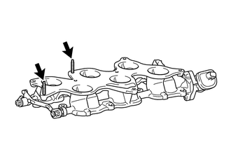
Using an E6 "TORX" socket wrench, remove the 2 stud bolts from the intake manifold.
-