INTAKE SYSTEM ON-VEHICLE INSPECTION
PROCEDURE
-
INSPECT INTAKE SYSTEM
Tech Tips
Perform "Inspection After Repair" after repairing vacuum leaks in the intake system.
-
Check that there are no vacuum leaks at the points shown in the illustration.
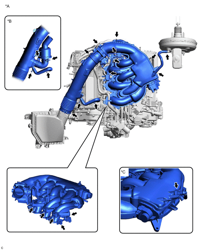
*A for LHD *B w/ Intake Air Sound Creator *C w/ Cold Start Fuel Injector - - 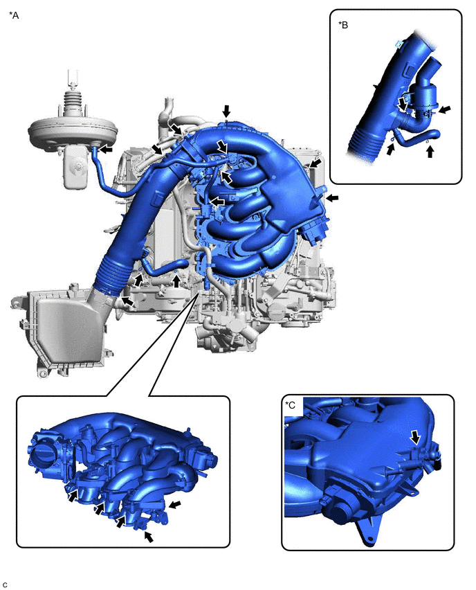
*A for RHD *B w/ Intake Air Sound Creator *C w/ Cold Start Fuel Injector - -
-
-
INSPECT INTAKE MANIFOLD (for SCV)
-
Remove the V-bank cover sub-assembly.
-
Check that the swirl control valve activation link (on the front of the intake manifold) is moving to confirm that the swirl control valve is operating.
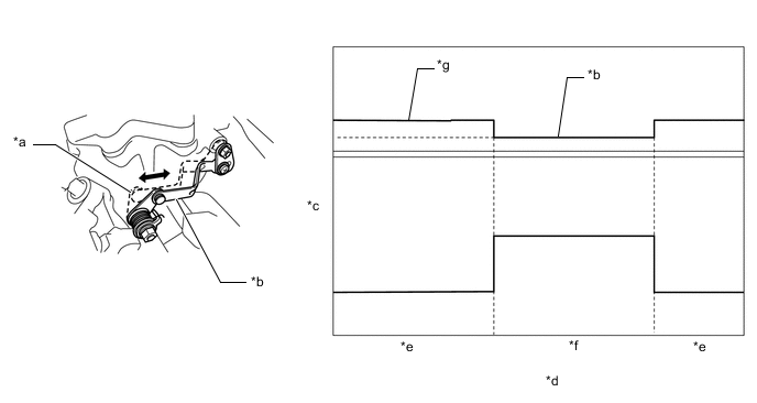
*a Open *b Fully Closed *c Valve Opening Angle *d Engine Condition *e OFF *f Idling *g Between approximately 10° and Fully Open - -
-
After the engine switch is turned off, confirm that the swirl control valve opens to between approximately 10° and the fully open position.
-
After the engine is started, confirm that the swirl control valve is fully closed with the engine idling.
-
After the engine switch is turned off again, confirm that the swirl control valve opens to between approximately 10° and the fully open position.
-
-
Inspection procedure when using the GTS:
-
Connect the GTS to the DLC3.
-
Turn the engine switch on (IG) and turn the GTS on.
-
Enter the following menus: Powertrain / Engine / Active Test / Control the SCV Duty Ratio.
Powertrain > Engine > Active TestTester Display Control the SCV Duty Ratio Note
This test procedure must be completed within 10 seconds.
-
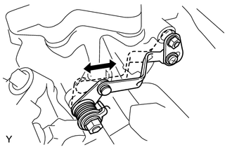
Check that the swirl control valve activation link (on the front of the intake manifold) moves to the left and right.
-
-
Inspection procedure when applying voltage between terminals:
-
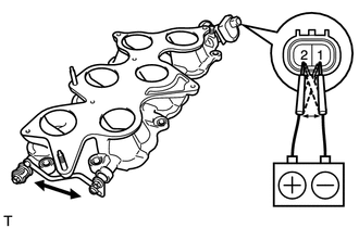
Disconnect the swirl control valve connector.
-
Alternately apply battery voltage to terminals 1 and 2 of the swirl control valve.
-
Check that the swirl control valve activation link (on the front of the intake manifold) moves to the left and right.
Note
Do not apply battery voltage for more than 30 seconds.
-
-
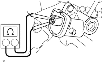
Measure the resistance between the terminals.
Standard Resistance 1 to 19 Ω at 20°C (68°F) If the result is not as specified, replace the intake manifold.
-
-
INSPECT FUNCTION OF AIR CLEANER FILTER ELEMENT SUB-ASSEMBLY
-
Check the air cleaner filter element sub-assembly.
Standard Condition Not excessively dirty. If the air cleaner filter element sub-assembly is excessively dirty, replace the air cleaner filter element sub-assembly.
-
Use compressed air if the air cleaner filter element sub-assembly needs to be cleaned.
-
-
PERFORM INITIALIZATION (w/ Canister Pump Module)
-
Perform "Inspection After Repair" after repairing vacuum leaks in the intake system.
-