INTERCOOLER INSTALLATION
PROCEDURE
-
INSTALL NO. 9 WATER BY-PASS HOSE
-
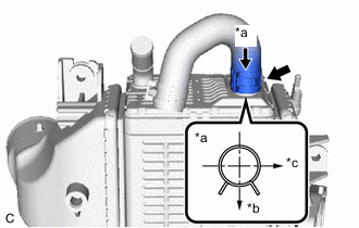
*a View A *b RH *c Front Install the No. 9 water by-pass hose to the intercooler assembly and slide the clip to secure it.
Tech Tips
Engage the clip within the area shown in the illustration.
-
-
INSTALL NO. 8 WATER BY-PASS HOSE
-
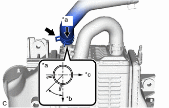
*a View A *b RH *c Front Install the No. 8 water by-pass hose to the intercooler assembly and slide the clip to secure it.
Tech Tips
Engage the clip within the area shown in the illustration.
-
Install the intercooler assembly to the vehicle.
-
-
SET INTERCOOLER ASSEMBLY
-
Set the intercooler assembly to the engine assembly.
-
-
INSTALL INTAKE MANIFOLD
-
Install 2 new intake manifold gaskets to the intake manifold.
-
Temporarily install the intake manifold to the cylinder head sub-assembly and cylinder block sub-assembly with the 4 bolts and 2 nuts.
-
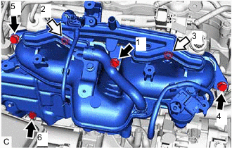

Bolt 
Nut Tighten the 4 bolts and 2 nuts in the order shown in the illustration.
- Torque:
- 21 N*m { 214 kgf*cm, 15 ft.*lbf }
-
-
CONNECT INLET HEATER WATER HOSE B
-
CONNECT VACUUM TRANSMITTING HOSE ASSEMBLY
-
CONNECT NO. 2 VACUUM TRANSMITTING HOSE ASSEMBLY
-
CONNECT NO. 3 WATER BY-PASS HOSE
-
CONNECT ENGINE WIRE
-
CONNECT OUTLET HEATER WATER HOSE A
-
CONNECT INLET HEATER WATER HOSE A
-
INSTALL NO. 2 WATER BY-PASS PIPE
-
INSTALL NO. 2 VENTILATION HOSE
-
INSTALL AIR CLEANER HOSE ASSEMBLY
-
INSTALL NO. 1 ENGINE COVER SUB-ASSEMBLY
-
INSTALL INTERCOOLER RESERVE TANK ASSEMBLY
-
INSTALL PURGE VALVE (PURGE VSV)
-
w/ Canister Pump Module:
-
w/o Canister Pump Module:
-
-
INSTALL INTERCOOLER ASSEMBLY
-
Install the intercooler assembly to the intercooler support bracket sub-assembly with the 3 bolts.
- Torque:
- 9.3 N*m { 95 kgf*cm, 82 in.*lbf }
-
-
CONNECT NO. 1 AIR TUBE
-
Connect the No. 1 air tube to the intercooler assembly and tighten the hose clamp.
- Torque:
- 6.3 N*m { 64 kgf*cm, 56 in.*lbf }
-
-
CONNECT ENGINE WIRE
-
Connect the engine wire with the bolt.
- Torque:
- 10 N*m { 102 kgf*cm, 7 ft.*lbf }
-
Engage the 2 clamps.
-
-
INSTALL HEATER WATER PUMP ASSEMBLY
-
Install the heater water pump assembly to the heater water pump bracket with the 2 bolts.
- Torque:
- 9.8 N*m { 100 kgf*cm, 87 in.*lbf }
-
-
CONNECT NO. 9 WATER BY-PASS HOSE
-

*a View A *b Rear *c Lower Connect the No. 9 water by-pass hose to the water by-pass pipe and slide the clip to secure it.
Tech Tips
Engage the clip within the area shown in the illustration.
-
-
CONNECT NO. 8 WATER BY-PASS HOSE
-
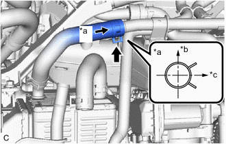
*a View A *b Upper *c RH Connect the No. 8 water by-pass hose to the No. 2 water by-pass pipe and slide the clip to secure it.
Tech Tips
Engage the clip within the area shown in the illustration.
-
-
CONNECT NO. 1 VACUUM TRANSMITTING HOSE
-
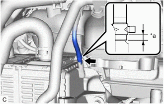
*a 2 to 5 mm (0.0787 to 0.197 in.) Connect the No. 1 vacuum transmitting hose assembly to the intercooler assembly and slide the clip to secure it as shown in the illustration.
-
-
CONNECT NO. 2 TURBO WATER HOSE
-
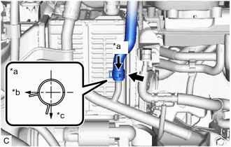
*a View A *b Front *c RH Connect the No. 2 turbo water hose to the water by-pass pipe and slide the clip to secure it.
Tech Tips
Engage the clip within the area shown in the illustration.
-
-
INSTALL THROTTLE BODY WITH MOTOR ASSEMBLY