EMISSION CONTROL SYSTEM(w/ Canister Pump Module) ON-VEHICLE INSPECTION
PROCEDURE
-
INSPECT FUEL CUT RPM
-
Start the engine.
-
Warm up the engine.
-
Increase the engine speed to approximately 3000 rpm.
-
Use a sound scope to check for injector operating sounds.
-
When the accelerator pedal is released, check that injector operating sounds stop momentarily and then resume.
Standard Item Specified Condition Fuel cut-off rpm 2500 rpm or higher Fuel injection restart rpm 1400 rpm If the result is not as specified, check the injectors, wiring and ECM.
-
-
VISUALLY INSPECT HOSES, CONNECTIONS AND GASKETS
-
Inspect the hoses and gaskets for scratches, cracks or air/oil leaks from the connecting parts.
Tech Tips
If the hoses or gaskets are damaged or some of the connections are loose, they may cause an engine stall or malfunction.
-
-
INSPECT EVAPORATIVE EMISSION CONTROL SYSTEM
-
Connect the GTS to the DLC3.
-
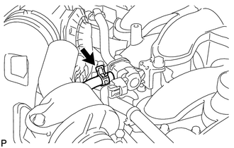
Disconnect the No. 2 fuel vapor feed hose from the purge valve (purge VSV).
-
Start the engine.
-
Enter the following menus: Powertrain / Engine / Active Test / Activate the VSV for Evap Control.
Powertrain > Engine > Active TestTester Display Activate the VSV for Evap Control -
Check that vacuum occurs at the purge valve (purge VSV) port.
-
If vacuum does not occur, check the following items.
-
Purge valve (purge VSV)
-
Clogging in the No. 2 fuel vapor feed hose that connects the intake air surge tank assembly and purge valve (purge VSV).
-
Voltage from the ECM PRG terminal.
-
-
Exit Active Test mode and reconnect the No. 2 fuel vapor feed hose.
-
Enter the following menus: Powertrain / Engine / Data List / EVAP (Purge) VSV.
Powertrain > Engine > Data ListTester Display EVAP (Purge) VSV -
Warm up the engine and drive the vehicle.
-
Confirm that the purge valve (purge VSV) opens.
If the result is not as specified, replace the purge valve (purge VSV), wire harness or ECM.
-
-
CHECK FUEL TANK AND VENT LINE
-
Disconnect the vent line hose from the canister (charcoal canister assembly).
-
Connect a pressure gauge to the vent line hose.
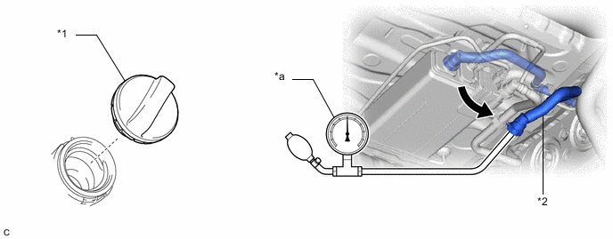
*1 Fuel Tank Cap Assembly *2 Vent Line Hose *a Pressure Gauge - - -
Apply 4 kPa (0.04 kgf/cm2, 0.6 psi) of pressure to the vent line of the fuel tank assembly.
Tech Tips
Perform this inspection with the fuel tank assembly less than 90% full. When the fuel tank assembly is full, the fuel fill check valve closes and the pressure is released through the 2 mm orifice. As a result, when the fuel tank cap assembly is removed, the pressure does not decrease smoothly.
-
Check that the fuel tank assembly pressure is maintained for some time and does not decrease immediately.
Tech Tips
If the pressure decreases immediately, one of the following may apply:
-
The fuel tank cap assembly is not completely tightened.
-
The fuel tank cap assembly is damaged.
-
Air is leaking from the vent line.
-
The fuel tank assembly is damaged.
-
-
When the fuel tank cap assembly is removed, check that the pressure is released smoothly.
If the pressure is not released smoothly, replace the fuel tank assembly.
-
Reconnect the vent line hose to the canister (charcoal canister assembly).
-
-
INSPECT AIR LINE
-
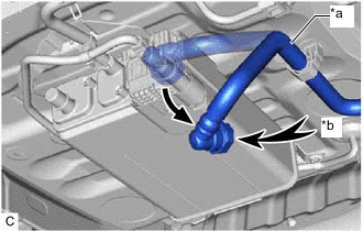
*a Air Line Tube *b Air Disconnect the air line tube from the leak detection pump sub-assembly.
-
Check that air flows freely into the air line.
If air does not flow freely into the air line, repair or replace the air line tube.
-
Reconnect the air line tube to the leak detection pump sub-assembly.
-