FUEL INJECTOR(for Direct Injection) REMOVAL

PROCEDURE
-
REMOVE FUEL PUMP ASSEMBLY (for High Pressure)
-
REMOVE NO. 2 FUEL PIPE SUB-ASSEMBLY
-
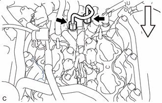

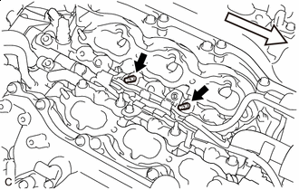
Front Using a 17 mm union nut wrench, loosen the 2 union nuts of the No. 2 fuel pipe sub-assembly.
-
Remove the No. 2 fuel pipe sub-assembly from the fuel delivery pipe with sensor assembly LH and fuel delivery pipe RH.
-
-
REMOVE FUEL DELIVERY PIPE WITH SENSOR ASSEMBLY LH
Note
-
Do not remove the fuel pressure sensor from the fuel delivery pipe with sensor assembly LH.
-
If the fuel pressure sensor is removed, replace the fuel pressure sensor (fuel delivery pipe with sensor assembly LH) with a new one.
-
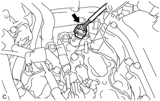
Disconnect the fuel pressure sensor connector.
-
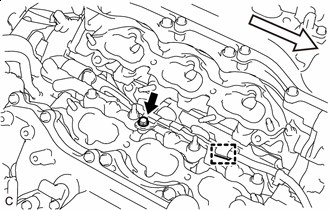
Front Remove the bolt.
-
Disengage the clamp to disconnect the No. 7 engine wire from the fuel delivery pipe with sensor assembly LH.
-
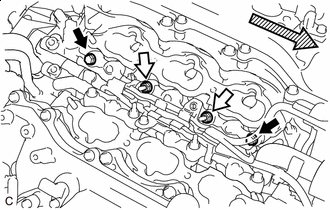

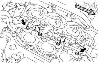
Bolt Nut 
Front Remove the 2 bolts and 2 nuts.
-
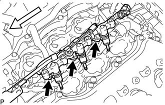
Front Using an E8 "TORX" socket wrench, remove the 2 stud bolts from the cylinder head LH.
-
Front With the connectors still connected, remove the fuel delivery pipe with sensor assembly LH.
Note
-
Make sure that the fuel delivery pipe is disconnected from the fuel delivery pipe with sensor assembly LH.
-
Be extremely careful not to touch or strike the tips of the fuel injector assemblies.
-
Pull and remove the fuel delivery pipe with sensor assembly LH in a straight line without tilting it.
-
-
Disconnect the 3 fuel injector assembly connectors and remove the No. 7 engine wire.
-
-
REMOVE FUEL DELIVERY PIPE RH
-
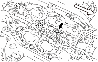
Front Remove the bolt.
-
Disengage the clamp to disconnect the No. 6 engine wire from the fuel delivery pipe RH.
-
Bolt Nut Front Remove the 2 bolts and 2 nuts.
-
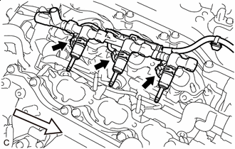
Front With the connectors still connected, remove the fuel delivery pipe RH.
Note
-
Be extremely careful not to touch or strike the tips of the fuel injector assemblies.
-
Pull and remove the fuel delivery pipe RH in a straight line without tilting it.
-
-
Disconnect the 3 fuel injector assembly connectors and remove the No. 6 engine wire.
-
-
REMOVE FUEL INJECTOR ASSEMBLY
-
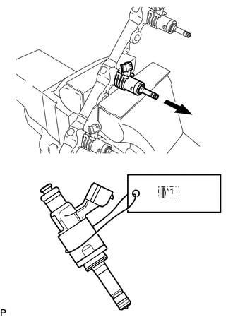
*1 No. 2 Secure the fuel delivery pipe with sensor assembly LH and fuel delivery pipe RH in a vise between aluminum plates and pull out the 6 fuel injector assemblies.
Note
-
Pull and remove each fuel injector assembly in a straight line to avoid damaging the seal surface of the fuel delivery pipe with sensor assembly LH and fuel delivery pipe RH O-ring.
-
After removing the fuel injector assemblies, remove any O-rings, No. 1 fuel injector back-up rings and No. 3 fuel injector back-up rings remaining on the fuel delivery pipe with sensor assembly LH and fuel delivery pipe RH side.
-
Attach a tag or label with the corresponding cylinder number to each fuel injector assembly so that they can be installed to their original locations.
-
-
Remove the nozzle holder clamp from each fuel injector assembly.
-
Using needle nose pliers, remove the No. 3 fuel injector back-up ring from each fuel injector assembly.
Note
Do not damage the area that contacts the O-ring.
-
Remove the O-ring and No. 1 fuel injector back-up ring from each fuel injector assembly.
-
Remove the C-ring and injector vibration insulator from each fuel injector assembly.
-
-
REMOVE FUEL INJECTOR SEAL
-
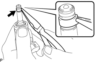
Using the tip of needle nose pliers, pinch and pull the fuel injector seal at several points to stretch it.
Note
-
Excessively pinching the fuel injector seal may damage the groove of the fuel injector assembly.
-
If a fuel injector assembly is dropped or the tip of the fuel injector assembly is struck, replace it with a new one.
-
-
Remove the fuel injector seal from each fuel injector assembly.
-