FUEL INJECTOR(for Port Injection) REMOVAL

PROCEDURE
-
PRECAUTION
Note
After turning the engine switch off, waiting time may be required before disconnecting the cable from the negative (-) battery terminal. Therefore, make sure to read the disconnecting the cable from the negative (-) battery terminal notices before proceeding with work.
-
DISCHARGE FUEL SYSTEM PRESSURE
-
DISCONNECT CABLE FROM NEGATIVE BATTERY TERMINAL
Note
When disconnecting the cable, some systems need to be initialized after the cable is reconnected.
-
REMOVE INTAKE AIR SURGE TANK ASSEMBLY
-
REMOVE NO. 2 FUEL TUBE SUB-ASSEMBLY
-
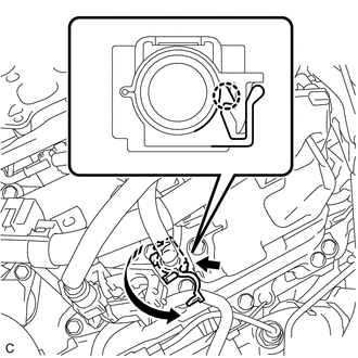
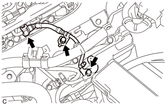
Disengage the claw to open the cover of the No. 1 fuel pipe clamp.
Note
Do not remove the No. 1 fuel pipe clamp from the fuel tube connector.
-
Disconnect the No. 2 fuel tube sub-assembly from the fuel pipe.
-
Disengage the claw to open the cover of the fuel hose clamp.
-
Remove the fuel hose clamp.
-
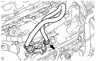
Remove the No. 2 fuel tube sub-assembly from the fuel pipe.
-
-
REMOVE NO. 1 ENGINE COVER SUB-ASSEMBLY
-
Remove the clip and No. 1 engine cover sub-assembly.
-
-
REMOVE NO. 1 FUEL TUBE SUB-ASSEMBLY
-
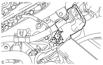
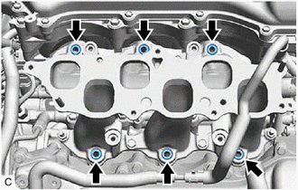
Remove the 2 bolts.
-
Remove the No. 1 fuel tube sub-assembly from the fuel delivery pipe with sensor assembly.
-
-
DISCONNECT WIRE HARNESS
-
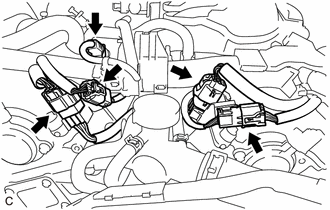
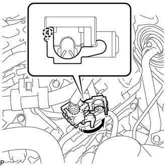
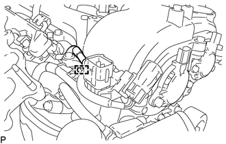
Disconnect the No. 5 engine wire connector, No. 6 engine wire connector, No. 7 engine wire connector, No. 8 engine wire connector and fuel pressure sensor connector.
-
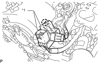
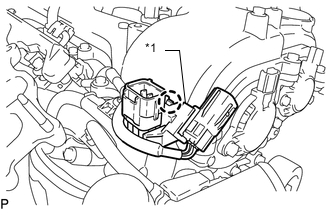
*1 No. 6 Engine Wire for Bank 1:
-
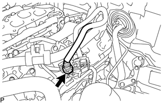
Disengage the claw and disconnect the No. 6 engine wire from the cylinder head cover sub-assembly.
-
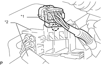
*1 No. 5 Engine Wire *2 No. 6 Engine Wire Disengage the claw and disconnect the No. 5 engine wire from the No. 6 engine wire.
-
-
*1 No. 7 Engine Wire for Bank 2:
-
Disengage the claw and disconnect the No. 7 engine wire from the cylinder head cover sub-assembly LH.
-
Disengage the clamp.
-

*1 No. 8 Engine Wire *2 No. 7 Engine Wire Disengage the claw and disconnect the No. 8 engine wire from the No. 7 engine wire.
-
-
-
REMOVE FUEL DELIVERY PIPE WITH SENSOR ASSEMBLY
Note
-
Do not remove the fuel pressure sensor from the fuel delivery pipe with sensor assembly.
-
If the fuel pressure sensor is removed, replace the fuel pressure sensor (fuel delivery pipe with sensor assembly) with a new one.
-
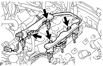
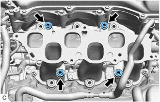
Remove the 4 bolts and fuel delivery pipe with sensor assembly from the intake manifold.
Note
When removing the fuel delivery pipe with sensor assembly, hold the pipe by both ends and pull it straight upward.
-
Remove the 4 No. 1 delivery pipe spacers from the intake manifold.
-
Remove the 6 injector vibration insulators from the intake manifold.
-
-
REMOVE FUEL INJECTOR ASSEMBLY
-
for Bank 2:
-
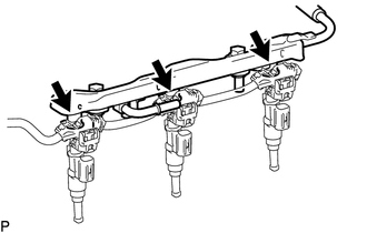
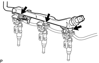
Remove the 3 fuel injector assemblies from the fuel delivery pipe with sensor assembly.
-
Disconnect the 3 connectors and remove the 3 fuel injector assemblies.
-
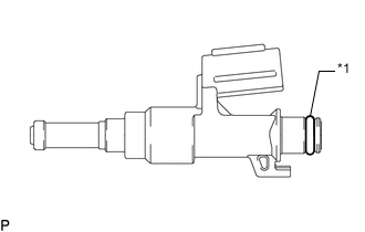
*1 O-ring Remove the O-ring from each fuel injector assembly.
-
-
for Bank 1:
-
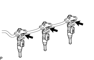
Remove the 3 fuel injector assemblies from the fuel delivery pipe with sensor assembly.
-
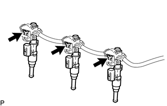
Disconnect the 3 connectors and remove the 3 fuel injector assemblies.
-
*1 O-ring Remove the O-ring from each fuel injector assembly.
-
-
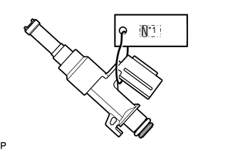
*1 No. 1 Attach a tag or label with the corresponding cylinder number to each fuel injector assembly so that they can be installed to their original locations.
Note
Cover the fuel injector assemblies with plastic bags to prevent damage and contamination.
-