FUEL PRESSURE SENSOR INSTALLATION

PROCEDURE
-
INSTALL FUEL PRESSURE SENSOR
-
Install a new gasket to the fuel pressure sensor.
-
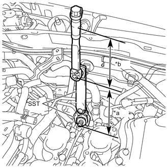
*a Length of SST 240 mm (9.45 in.) *b Length of Torque Wrench 180 mm (7.09 in.) Using SST, install the fuel pressure sensor to the No. 1 delivery pipe sub-assembly.
- SST
- 09922-10240
- Torque:
- without SST [Torque (N*m (kgf*cm, ft.*lbf))]
- 42 N*m { 428 kgf*cm, 31 ft.*lbf }
- with SST [Reading of Torque wrench (N*m (kgf*cm, ft.*lbf))]
- 18 N*m { 184 kgf*cm, 13 ft.*lbf }
Tech Tips
-
This torque value is effective when SST is parallel to the torque wrench.
-
The "with SST" torque value is effective when using SST with a fulcrum length of 240 mm (9.45 in.).
-
The "with SST" torque value is effective when using a torque wrench with a fulcrum length of 180 mm (7.09 in.).
-
If using a torque wrench with a different length, or connecting the torque wrench and SST at an angle, refer to the alternate torque values.
-
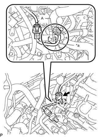
*a Wire Harness Connect the fuel pressure sensor connector and wire harness clamp.
Note
-
Make sure the wire harness of the fuel pressure sensor passes under the area (A) as shown in the illustration.
-
Do not pull the wire harness of the fuel pressure sensor excessively.
-
-
-
INSTALL NO. 3 WATER BY-PASS PIPE
-
Connect the No. 8 water by-pass hose and No. 9 water by-pass hose to the No. 3 water by-pass pipe and slide the 2 clips to secure them.
-
Install the No. 3 water by-pass pipe to the camshaft housing sub-assembly RH with the bolt.
- Torque:
- 10 N*m { 102 kgf*cm, 7 ft.*lbf }
-
Engage the wire harness clamp to the No. 3 water by-pass pipe.
-
Connect the inlet heater water hose A and outlet heater water hose A to the No. 3 water by-pass pipe and slide the 2 clips to secure them.
-
-
INSTALL FUEL RELIEF VALVE ASSEMBLY