FUEL SENDER GAUGE ASSEMBLY INSTALLATION

PROCEDURE
-
INSTALL NO. 2 FUEL SENDER GAUGE ASSEMBLY
-
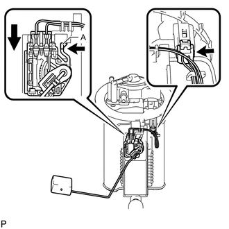
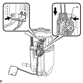
Slide the No. 2 fuel sender gauge assembly downwards and engage the claw (A) to install the No. 2 fuel sender gauge assembly.
-
Connect the No. 2 fuel sender gauge assembly connector.
Note
-
Do not touch the resistance plate or contacts of the No. 2 fuel sender gauge assembly.
-
Do not bend the arm of the No. 2 fuel sender gauge assembly.
-
-
-
INSTALL FUEL TANK VENT TUBE ASSEMBLY
-
Install a new fuel suction tube set gasket to the fuel tank assembly.
-
Connect the fuel return vent tube sub-assembly and set the fuel tank vent tube assembly on the fuel tank assembly.
Note
-
Do not bend the arm of the No. 2 fuel sender gauge assembly.
-
When connecting the fuel tube connector, do not excessively pull on the fuel return vent tube sub-assembly.
-
-
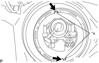
*a Protrusion 
Notch Align the protrusions of the fuel tank vent tube assembly with the notches in the fuel tank assembly.
-
While pressing down on the fuel tank vent tube assembly with your hand, temporarily install the fuel pump gauge retainer.
-
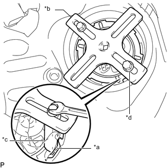
*a Insertion Point *b SST (Plate) *c SST (Claw) *d SST (Bolt) Temporarily install SST (plate and claws) to the fuel pump gauge retainer.
- SST
- 09808-14030 ( 09808-01010, 09808-01030, 09808-01050 )
Tech Tips
Securely insert the ends of SST (claws) into the insertion points in the fuel pump gauge retainer.
-
While firmly pressing the SST (claws) into the insertion points in the fuel pump gauge retainer, tighten the SST (bolts).
-
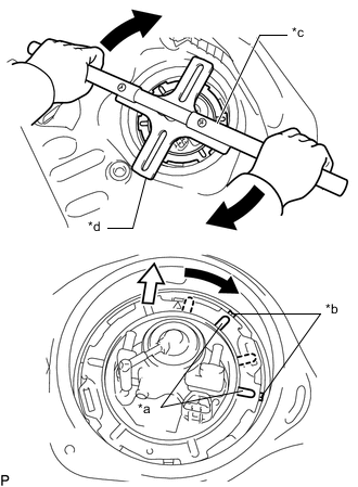
*a Protrusion *b Groove *c SST (Handle) *d SST (Plate) 
Front Side Using SST, rotate the fuel pump gauge retainer so that the protrusions of the retainer are aligned with the grooves in the fuel tank assembly to install the fuel suction tube with pump and gauge assembly to the fuel tank assembly.
Note
-
Do not use any tools other than specified in this operation as this may result in damage to the fuel pump gauge retainer or the fuel tank assembly.
-
Do not press down on SST excessively as this may make the retainer hard to rotate, and may damage components.
-
Make sure to rotate SST (handle) horizontally. If it is rotated at an angle, SST may come off.
-
Do not spin SST too fast or use an impact wrench as this may result in damage to components.
-
If SST comes off of the fuel pump gauge retainer, loosen SST (bolts) and reinstall SST.
-
Make sure that the fuel suction tube set gasket does not come off.
-
-
Install the No. 1 fuel tube clamp to the fuel suction tube with pump and gauge assembly.
-
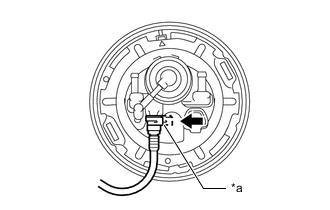
*a Retainer Push Align the fuel tank EVAP/VENT tube with the fuel tank vent tube assembly, and push them together until the fuel tube connector makes a "click" sound.
Note
-
Check if there is any damage or foreign matter on the connecting parts of the fuel lines.
-
After connecting the fuel tank EVAP/VENT tube, check that the fuel tank EVAP/VENT tube is securely connected by pulling on it.
-
-
Connect the charcoal canister outlet hose to the fuel tank vent tube assembly.
-
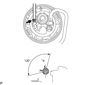
*a Upper Connect the No. 1 fuel evaporation tube sub-assembly to the fuel tank vent tube assembly and slide the clip to secure it.
Tech Tips
Engage the clip within the area shown in the illustration.
-
-
INSTALL REAR FLOOR SERVICE HOLE COVER
-
Connect the No. 2 fuel sender gauge assembly connector.
-
Install the rear floor service hole cover with new butyl tape.
-
-
INSTALL FUEL SENDER GAUGE ASSEMBLY
-
Slide the fuel sender gauge assembly downwards and engage the claw (A) to install the fuel sender gauge assembly.
-
Connect the fuel sender gauge assembly connector.
Note
-
Do not touch the resistance plate or contacts of the fuel sender gauge assembly.
-
Do not bend the arm of the fuel sender gauge assembly.
-
-
-
INSTALL FUEL SUCTION TUBE WITH PUMP AND GAUGE ASSEMBLY