FUEL PUMP INSTALLATION

PROCEDURE
-
INSTALL FUEL SUCTION TUBE WITH PUMP AND GAUGE ASSEMBLY
-
Install a new fuel suction tube set gasket onto the fuel tank assembly.
-
Connect the fuel return vent tube sub-assembly and set the fuel suction tube with pump and gauge assembly into the fuel tank assembly.
Note
-
Make sure that the fuel sender gauge assembly arm does not bend.
-
When connecting the fuel tube connector, do not forcibly pull the fuel return vent tube sub-assembly.
-
-
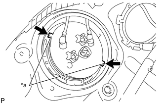
*a Protrusion 
Notch Align the protrusions of the fuel suction tube with pump and gauge assembly with the notches in the fuel tank assembly.
-
-
INSTALL FUEL PUMP GAUGE RETAINER
-
While pressing down on the fuel suction tube with pump and gauge assembly, temporarily install a new fuel pump gauge retainer.
-
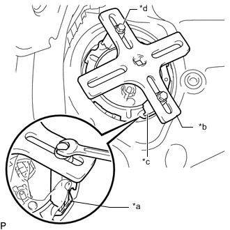
*a Insertion Point *b SST (Plate) *c SST (Claw) *d SST (Bolt) Temporarily install SST (plate and claws) to the fuel pump gauge retainer.
- SST
- 09808-14030 ( 09808-01030, 09808-01040, 09808-01050, 09808-01010 )
Tech Tips
Securely insert the ends of SST (claws) into the insertion points in the fuel pump gauge retainer.
-
While firmly pressing the SST (claws) into the insertion points in the fuel pump gauge retainer, tighten the SST (bolts).
-
Install SST (handle).
-
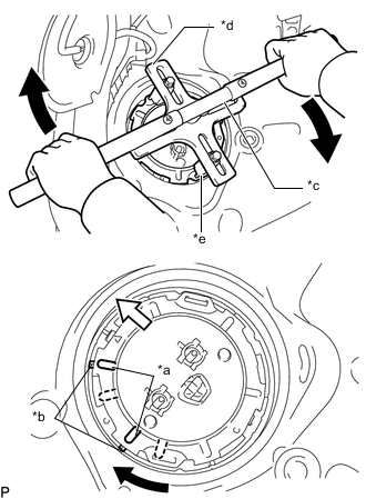
*a Protrusion *b Groove *c SST (Handle) *d SST (Plate) *e SST (Claw) 
Front Side Using SST, rotate the fuel pump gauge retainer so that the protrusions of the retainer are aligned with the grooves in the fuel tank assembly to install the fuel suction tube with pump and gauge assembly to the fuel tank assembly.
Note
-
Do not use any tools other than specified in this operation as this may result in damage to the fuel pump gauge retainer or the fuel tank assembly.
-
Do not press down on SST excessively as this may make the retainer hard to rotate, and may damage components.
-
Make sure to rotate SST (handle) horizontally. If it is rotated at an angle, SST may come off.
-
Do not spin SST too fast or use an impact wrench as this may result in damage to components.
-
If SST comes off of the fuel pump gauge retainer, loosen SST (bolts) and reinstall SST.
-
Make sure that the fuel suction tube set gasket does not come off.
-
-
Install the No. 1 fuel tube clamp to the fuel suction tube with pump and gauge assembly.
-
-
CONNECT FUEL TANK RETURN TUBE
-
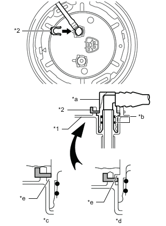
*1 Fuel Suction Plate Sub-assembly *2 Tube Joint Clip *a Fuel Tube Joint *b O-ring *c Correct *d Incorrect *e Collar Push the fuel tank return tube onto the plug of the fuel suction plate, then install the tube joint clip.
Note
-
Check that there are no scratches or foreign matter around the connecting parts of the fuel tube joint and plug before performing this work.
-
Check that the plug is securely inserted to the end of the fuel tube joint.
-
Check that the tube joint clip is on the collar of the fuel tube joint.
-
After installing the tube joint clip, check that the fuel tank return tube cannot be pulled out.
-
-
-
CONNECT FUEL TANK MAIN TUBE SUB-ASSEMBLY
-
*1 Fuel Suction Plate Sub-assembly *2 Tube Joint Clip *a Fuel Tube Joint *b O-ring *c Correct *d Incorrect *e Collar Push the fuel tank main tube sub-assembly onto the plug of the fuel suction plate, then install the tube joint clip.
Note
-
Check that there are no scratches or foreign matter around the connecting parts of the fuel tube joint and plug before performing this work.
-
Check that the plug is securely inserted to the end of the fuel tube joint.
-
Check that the tube joint clip is on the collar of the fuel tube joint.
-
After installing the tube joint clip, check that the fuel tank main tube sub-assembly cannot be pulled out.
-
-
Connect the fuel pump connector.
-
-
CONNECT CABLE TO NEGATIVE BATTERY TERMINAL
Note
When disconnecting the cable, some systems need to be initialized after the cable is reconnected.
-
INSPECT FOR FUEL LEAK
-
INSTALL REAR FLOOR SERVICE HOLE COVER
-
Install the rear floor service hole cover with new butyl tape.
-
-
INSTALL REAR SEAT CUSHION LOCK HOOK
-
INSTALL REAR SEAT CUSHION ASSEMBLY