ENGINE UNIT REMOVAL

PROCEDURE
-
REMOVE INTAKE AIR SURGE TANK ASSEMBLY
-
REMOVE FRONT NO. 1 ENGINE MOUNTING BRACKET LH
-
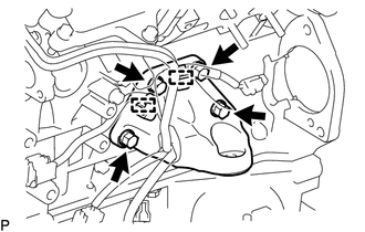
Disengage the 2 clamps.
-
Remove the 4 bolts and front No. 1 engine mounting bracket LH.
-
-
REMOVE FRONT NO. 1 ENGINE MOUNTING BRACKET RH
-
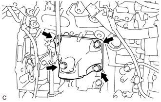
Remove the 4 bolts and front No. 1 engine mounting bracket RH.
-
-
REMOVE V-RIBBED BELT
-
REMOVE GENERATOR ASSEMBLY
-
REMOVE COMPRESSOR AND MAGNETIC CLUTCH
-
REMOVE NO. 1 COMPRESSOR MOUNTING BRACKET
-
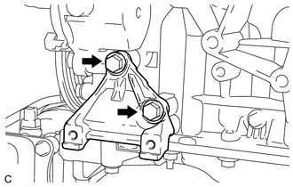
Remove the 2 bolts and No. 1 compressor mounting bracket.
-
-
REMOVE NO. 2 IDLER PULLEY SUB-ASSEMBLY
-
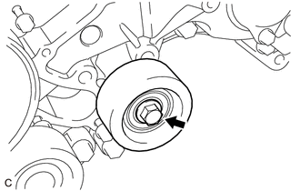
Remove the bolt and No. 2 idler pulley sub-assembly.
-
-
REMOVE V-RIBBED BELT TENSIONER ASSEMBLY
-
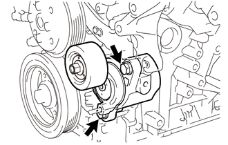
Remove the 2 bolts and V-ribbed belt tensioner assembly.
-
-
REMOVE ENGINE WIRE
-
Remove the engine wire from the engine assembly.
-
-
REMOVE NO. 6 WATER BY-PASS HOSE
-
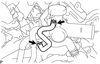
Slide the 2 clips and remove the No. 6 water by-pass hose from the water outlet and cylinder head sub-assembly.
-
-
REMOVE NO. 2 WATER BY-PASS HOSE
-
Slide the 2 clips and remove the No. 2 water by-pass hose.
-
-
REMOVE NO. 3 WATER BY-PASS HOSE
-
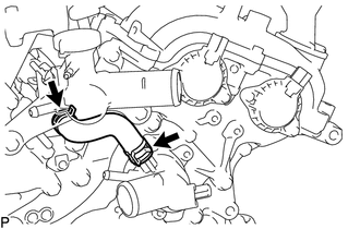
Slide the 2 clips and remove the No. 3 water by-pass hose.
-
-
REMOVE NO. 2 WATER BY-PASS HOSE ASSEMBLY
-
Slide the 2 clips and remove the No. 2 water by-pass hose assembly.
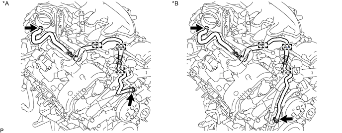
*A w/o Oil Cooler *B w/ Oil Cooler -
Disengage the 3 clamps.
-
-
REMOVE WATER BY-PASS HOSE
-
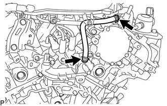
Slide the 2 clips and remove the water by-pass hose.
-
-
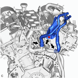
REMOVE NO. 1 WATER BY-PASS PIPE (w/ Oil Cooler)
-
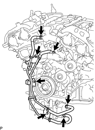
Slide the 4 clips and disconnect the 4 water by-pass hoses.
-
Remove the 2 bolts, nut and No. 1 water by-pass pipe.
-
-
REMOVE WATER INLET CAP (w/o Oil Cooler)
-
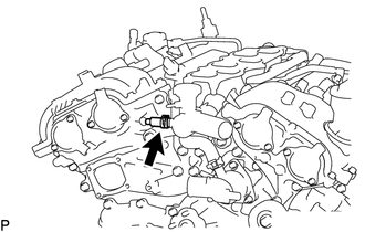
Slide the clip and remove the water inlet cap.
-
-
REMOVE NO. 2 WATER BY-PASS PIPE
-
Remove the bolt.
-
Slide the 2 clips and remove the No. 2 water by-pass pipe.
-
-
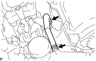
REMOVE NO. 10 WATER BY-PASS HOSE
-
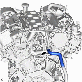
Slide the clip and remove the No. 10 water by-pass hose from the rear water by-pass joint.
-
-
REMOVE NO. 11 WATER BY-PASS HOSE
-
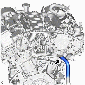
Slide the clip and remove the No. 11 water by-pass hose from the No. 1 water outlet pipe.
-
-
REMOVE WIRE HARNESS CLAMP BRACKET
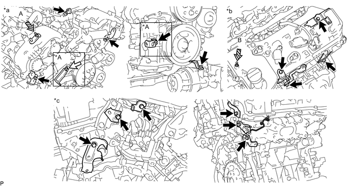
*A w/o Oil Cooler - - *a Front Side *b Upper Side *c Rear Side - - 
Bolt 
Nut 
V-bank Cover Bracket - -
-
Remove the V-bank cover bracket (A) and wire harness clamp bracket.
-
Remove the V-bank cover bracket (B).
-
Remove the 14 bolts and 14 wire harness clamp brackets.
-
w/o Oil Cooler:
-
Remove the nut and wire harness clamp bracket.
-
Remove the bolt and wire harness clamp bracket.
-
-
-
REMOVE WATER PUMP PULLEY
-
REMOVE FUEL DELIVERY PIPE WITH SENSOR ASSEMBLY
-
REMOVE FUEL INJECTOR ASSEMBLY (for Port Injection)
-
REMOVE INTAKE MANIFOLD
-
REMOVE NO. 1 FUEL PIPE SUB-ASSEMBLY
-
REMOVE FUEL PUMP ASSEMBLY
-
REMOVE NO. 2 FUEL PIPE SUB-ASSEMBLY
-
REMOVE FUEL DELIVERY PIPE WITH SENSOR ASSEMBLY LH
-
REMOVE FUEL DELIVERY PIPE RH
-
REMOVE FUEL INJECTOR ASSEMBLY (for Direct Injection)
-
REMOVE FUEL INJECTOR SEAL
-
REMOVE IGNITION COIL ASSEMBLY
-
REMOVE ENGINE OIL PRESSURE SWITCH ASSEMBLY
-
REMOVE ENGINE COOLANT TEMPERATURE SENSOR