CYLINDER HEAD GASKET REMOVAL
PROCEDURE
-
REMOVE TIMING CHAIN COVER ASSEMBLY
-
SET NO. 1 CYLINDER TO TDC/COMPRESSION
-
Temporarily install the pulley set bolt.
-
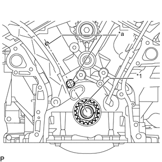
*1 Crankshaft Pulley Set Key *a Center Mark Set the crankshaft pulley set key to the RH block bore center mark (TDC/compression).
-
*a Timing Mark Set the crankshaft pulley set key to the RH block bore center mark (TDC/compression). If not, turn the crankshaft 1 revolution (360°) and align the timing marks as above.
-
-
REMOVE NO. 1 CHAIN TENSIONER ASSEMBLY
-
REMOVE CHAIN TENSIONER SLIPPER
-
REMOVE CHAIN SUB-ASSEMBLY
-
REMOVE CAMSHAFT TIMING GEARS AND NO. 2 CHAIN (for Bank 1)
-
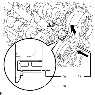
*a Pin *b Plunger *c Push While raising the No. 2 chain tensioner assembly, insert a pin of 1.0 mm (0.0394 in.) diameter into the hole to hold the No. 2 chain tensioner assembly.
-
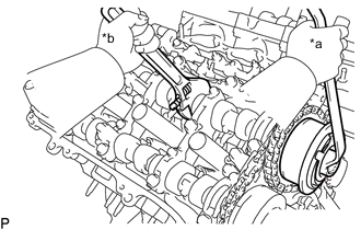
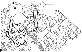
*a Turn *b Hold Using a wrench to hold the hexagonal portion of each camshaft, loosen the camshaft timing gear bolt of the camshaft timing gear assembly.
Note
-
Be careful not to damage the cylinder head with the wrench.
-
Do not loosen the other bolts. If any of the bolts is loosened, replace the camshaft timing gear assembly and/or the camshaft timing exhaust gear assembly with a new one.
-
-
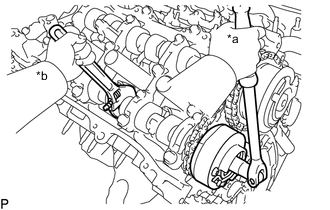
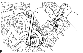
*a Turn *b Hold Using a wrench to hold the hexagonal portion of each camshaft, loosen the camshaft timing gear bolt of the camshaft timing exhaust gear assembly RH.
Note
-
Be careful not to damage the cylinder head with the wrench.
-
Do not loosen the other bolts. If any of the bolts is loosened, replace the camshaft timing gear assembly and/or the camshaft timing exhaust gear assembly with a new one.
-
-
Remove the 2 bolts and the camshaft timing gear assembly together with the No. 2 chain.
-
-
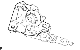
REMOVE NO. 2 CHAIN TENSIONER ASSEMBLY
-
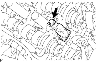
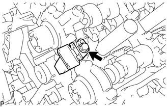
Remove the bolt and No. 2 chain tensioner assembly.
-
-
REMOVE CAMSHAFT BEARING CAP (for Bank 1)
-
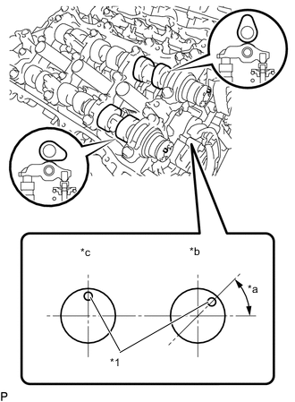
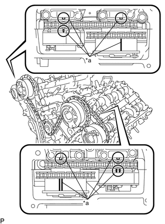
*1 Knock Pin *a 45° *b Intake Side *c Exhaust Side Check that the camshafts are positioned as shown in the illustration.
-
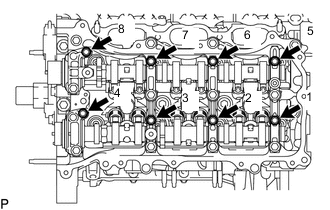
Uniformly loosen and remove the 9 bolts in several steps and in the sequence shown in the illustration.
-
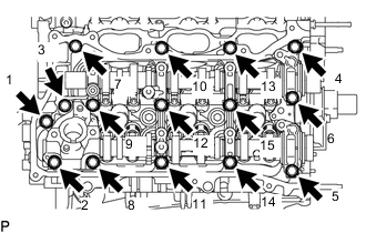
Uniformly loosen and remove the 15 bolts in several steps and in the sequence shown in the illustration.
Note
Uniformly loosen the bolts while keeping the camshaft level.
-
-
REMOVE FUEL PUMP LIFTER HOUSING
-
Remove the fuel pump lifter housing.
-
-
REMOVE CAMSHAFT
-
Remove the camshaft from the camshaft housing sub-assembly RH.
-
-
REMOVE NO. 2 CAMSHAFT
-
Remove the camshaft No. 2 from the camshaft housing sub-assembly RH.
-
-
REMOVE CAMSHAFT HOUSING SUB-ASSEMBLY RH
-
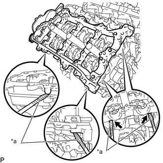
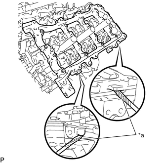
*a Protective Tape Remove the camshaft housing RH by prying between the cylinder head and camshaft housing RH with a screwdriver.
Note
Be careful not to damage the contact surfaces of the cylinder head and camshaft housing RH.
Tech Tips
Tape the screwdriver tip before use.
-
-
REMOVE CAMSHAFT TIMING GEARS AND NO. 2 CHAIN (for Bank 2)
-
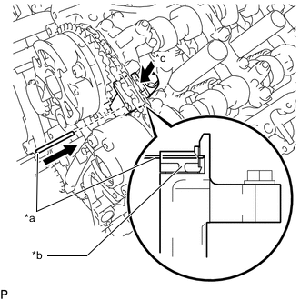
*a Pin *b Plunger *c Push While pushing down the No. 3 chain tensioner assembly, insert a pin of 1.0 mm (0.0394 in.) diameter into the hole to hold the No. 3 chain tensioner assembly.
-
*a Turn *b Hold Using a wrench to hold the hexagonal portion of each camshaft sub-assembly No. 3, loosen the camshaft timing gear bolt of the camshaft timing gear assembly.
Note
-
Be careful not to damage the cylinder head with the wrench.
-
Do not loosen the other bolts. If any of the bolts is loosened, replace the camshaft timing gear assembly and/or the camshaft timing exhaust gear assembly LH with a new one.
-
-
*a Turn *b Hold Using a wrench to hold the hexagonal portion of each camshaft sub-assembly No. 4, loosen the camshaft timing gear bolt of the camshaft timing exhaust gear assembly LH.
Note
-
Be careful not to damage the cylinder head with the wrench.
-
Do not loosen the other bolts. If any of the bolts is loosened, replace the camshaft timing gear assembly and/or the camshaft timing exhaust gear assembly LH with a new one.
-
-
Remove the 2 bolts and the camshaft timing gear together with the No. 2 chain sub-assembly.
-
-
REMOVE NO. 3 CHAIN TENSIONER ASSEMBLY
-
Remove the bolt and No. 3 chain tensioner assembly.
-
-
REMOVE CAMSHAFT BEARING CAP (for Bank 2)
-
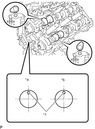
*1 Knock Pin *a Intake Side *b Exhaust Side Check that the camshafts are positioned as shown in the illustration.
-
Uniformly loosen and remove the 8 bolts in several steps and in the sequence shown in the illustration.
-
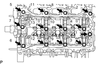
Uniformly loosen and remove the 13 bolts in several steps and in the sequence shown in the illustration.
Note
Uniformly loosen the bolts while keeping the camshaft level.
-
Remove the 5 camshaft bearing caps.
-
-
REMOVE NO. 3 CAMSHAFT SUB-ASSEMBLY
-
Remove the No. 3 camshaft sub-assembly from the camshaft housing sub-assembly LH.
-
-
REMOVE NO. 4 CAMSHAFT SUB-ASSEMBLY
-
Remove the No. 4 camshaft sub-assembly from the camshaft housing sub-assembly LH.
-
-
REMOVE CAMSHAFT HOUSING SUB-ASSEMBLY LH
-
*a Protective Tape Remove the camshaft housing sub-assembly LH by prying between the cylinder head LH and camshaft housing sub-assembly LH with a screwdriver.
Note
Be careful not to damage the contact surfaces of the cylinder head and camshaft housing sub-assembly LH.
Tech Tips
Protective tape the screwdriver tip before use.
-
-
REMOVE NO. 1 CHAIN VIBRATION DAMPER
-
REMOVE NO. 2 CHAIN VIBRATION DAMPER
-
REMOVE NO. 1 VALVE ROCKER ARM SUB-ASSEMBLY
-
Remove the 24 No. 1 valve rocker arm sub-assemblies.
Tech Tips
Arrange the removed parts in the correct order.
-
-
REMOVE VALVE LASH ADJUSTER ASSEMBLY
-
Remove the 24 valve lash adjuster assemblies.
Tech Tips
Arrange the removed parts in the correct order.
-
-
REMOVE VALVE STEM CAP
-
Remove the 24 valve stem caps.
Tech Tips
Arrange the removed parts in the correct order.
-
-
REMOVE REAR WATER BY-PASS JOINT
-
REMOVE NO. 2 FUEL PIPE SUB-ASSEMBLY
-
REMOVE FUEL DELIVERY WITH SENSOR PIPE ASSEMBLY LH
-
REMOVE FUEL DELIVERY PIPE RH
-
REMOVE FUEL INJECTOR ASSEMBLY (for Direct Injection)
-
REMOVE FUEL INJECTOR SEAL
-
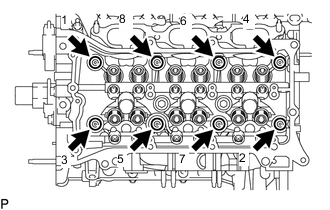
REMOVE CYLINDER HEAD SUB-ASSEMBLY
-
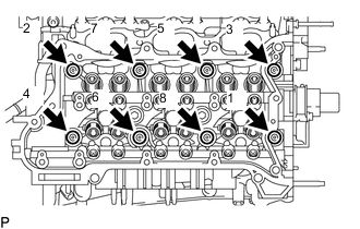
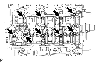
Using a 10 mm bi-hexagon wrench, uniformly loosen the 8 bolts in the sequence shown in the illustration. Remove the 8 bolts and plate washers.
Note
-
Be careful not to drop plate washers into the cylinder head sub-assembly.
-
Cylinder head warpage or cracking could result from removing bolts in an incorrect order.
Tech Tips
Be sure to keep separate the removed parts for each installation position.
-
-
Remove the cylinder head sub-assembly.
-
-
REMOVE CYLINDER HEAD GASKET
-
Remove the cylinder head gasket from the cylinder block sub-assembly.
-
-
REMOVE CYLINDER HEAD LH
-
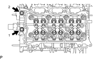
Uniformly loosen and remove the 2 bolts in the sequence shown in the illustration.
-
Using a 10 mm bi-hexagon wrench, uniformly loosen the 8 bolts in the sequence shown in the illustration. Remove the 8 bolts and plate washers.
Note
-
Be careful not to drop plate washers into the cylinder head LH.
-
Cylinder head warpage or cracking could result from removing bolts in an incorrect order.
Tech Tips
Be sure to keep separate the removed parts for each installation position.
-
-
Remove the cylinder head LH.
-
-
REMOVE NO. 2 CYLINDER HEAD GASKET
-
Remove the No. 2 cylinder head gasket from the cylinder block sub-assembly.
-
-
INSPECT CYLINDER HEAD SET BOLT
-
INSPECT CYLINDER HEAD SUB-ASSEMBLY