ENGINE ASSEMBLY REMOVAL
CAUTION / NOTICE / HINT
CAUTION:
The engine assembly with transmission is very heavy. Be sure to follow the procedure described in the repair manual, or the engine lifter may suddenly drop.
PROCEDURE
-
PRECAUTION
Note
After turning the engine switch off, waiting time may be required before disconnecting the cable from the negative (-) battery terminal. Therefore, make sure to read the disconnecting the cable from the negative (-) battery terminal notices before proceeding with work.
-
REMOVE COOL AIR INTAKE DUCT SEAL
-
REMOVE V-BANK COVER SUB-ASSEMBLY
-
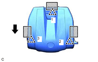

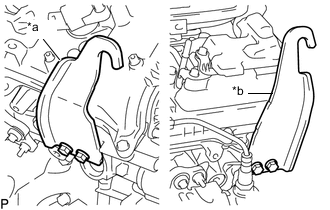
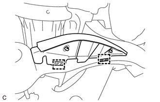
Areas to be held when lifting the V-bank cover sub-assembly 
Front of Engine Hold the rear area of the V-bank cover sub-assembly shown in the illustration and detach the rear clip (1).
Note
If the V-bank cover sub-assembly is lifted rearward or forward and to the right or left at the same time, the V-bank cover sub-assembly may be damaged.
-
Hold both sides of the V-bank cover sub-assembly and lift it to detach the 2 front clips (2) and (3) to remove the V-bank cover sub-assembly.
-
-
RECOVER REFRIGERANT FROM REFRIGERATION SYSTEM
-
DISCHARGE FUEL SYSTEM PRESSURE
-
PLACE FRONT WHEELS FACING STRAIGHT AHEAD
-
SECURE STEERING WHEEL
-
REMOVE FRONT WHEELS
-
DISCONNECT CABLE FROM NEGATIVE BATTERY TERMINAL
Note
When disconnecting the cable, some systems need to be initialized after the cable is reconnected.
-
REMOVE ENGINE UNDER COVER
-
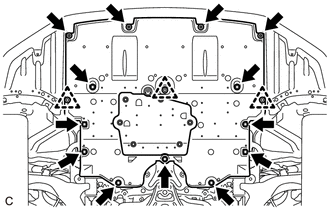
Remove the 13 screws, 3 clips and engine under cover.
-
-
REMOVE REAR ENGINE UNDER COVER LH
-
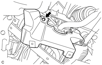
Remove the screw and rear engine under cover LH.
-
-
REMOVE REAR ENGINE UNDER COVER RH
-
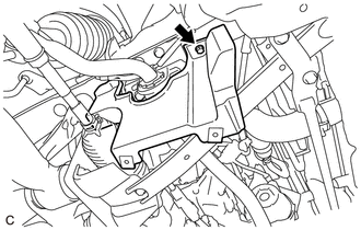
Remove the screw and rear engine under cover RH.
-
-
REMOVE FRONT SUSPENSION MEMBER BRACE
-
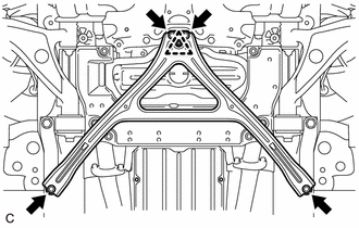
Remove the 4 bolts, turn the clip to loosen it, and remove the front suspension member brace.
Tech Tips
Do not remove the clip from the front suspension member brace.
-
-
REMOVE NO. 2 ENGINE UNDER COVER
-
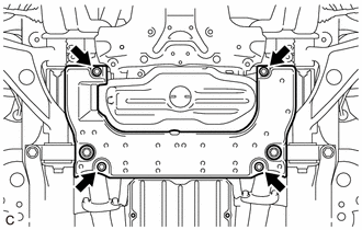
Remove the 4 screws and No. 2 engine under cover.
-
-
DRAIN ENGINE OIL
-
DRAIN ENGINE COOLANT
-
DRAIN AUTOMATIC TRANSMISSION FLUID
-
REMOVE INLET NO. 1 AIR CLEANER
-
Remove the bolt and inlet No. 1 air cleaner.
-
-
REMOVE AIR CLEANER CAP WITH AIR CLEANER HOSE
Tech Tips
Perform this procedure only when replacement of the air cleaner filter element sub-assembly or air cleaner case sub-assembly is necessary.
-
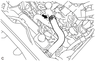
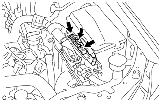
Slide the clip and disconnect the No. 2 ventilation hose.
-
Disconnect the mass air flow meter sub-assembly connector.
-
Disconnect the wire harness clamp from the air cleaner cap with air cleaner hose.
-
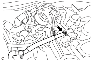
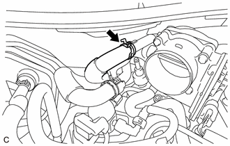
Disengage the clamp to disconnect the No. 1 fuel vapor feed hose from the air cleaner cap with air cleaner hose.
-
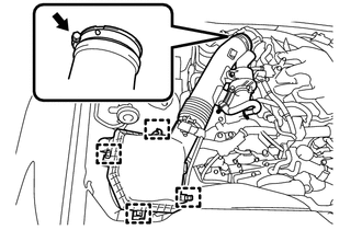
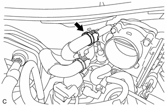
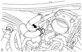
Release the 4 clamps.
-
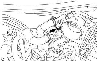
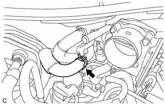
Loosen the hose clamp and remove the air cleaner cap with air cleaner hose from the throttle body with motor assembly.
-
-
REMOVE AIR CLEANER FILTER ELEMENT SUB-ASSEMBLY
Tech Tips
Perform this procedure only when replacement of the air cleaner filter element sub-assembly is necessary.
-
Remove the air cleaner filter element sub-assembly from the air cleaner case sub-assembly.
-
-
REMOVE AIR CLEANER CASE SUB-ASSEMBLY
Tech Tips
Perform this procedure only when replacement of the air cleaner case sub-assembly is necessary.
-
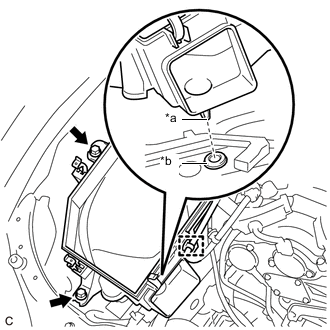
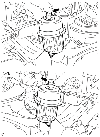
*a Pin *b Air Cleaner Support Disconnect the wire harness clamp from the air cleaner case sub-assembly.
-
Remove the 2 bolts and air cleaner case sub-assembly.
Note
Make sure the air cleaner support is attached to the vehicle body.
-
-
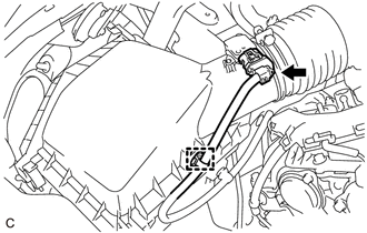
REMOVE AIR CLEANER ASSEMBLY WITH AIR CLEANER HOSE
-
Disconnect the mass air flow meter sub-assembly connector.
-
Disconnect the 2 wire harness clamps from the air cleaner assembly with air cleaner hose.
-
Disengage the clamp to disconnect the No. 1 fuel vapor feed hose from the air cleaner assembly with air cleaner hose.
-
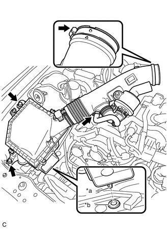
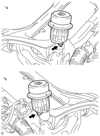
*a Pin *b Air Cleaner Support Remove the 2 bolts.
-
Slide the clip and disconnect the No. 2 ventilation hose from the air cleaner assembly with air cleaner hose.
-
Loosen the hose clamp and remove the air cleaner assembly with air cleaner hose.
Note
Make sure the air cleaner support is attached to the vehicle body.
-
-
DISCONNECT UNION TO CONNECTOR TUBE HOSE (for LHD)
-
Slide the clip and disconnect the union to connector tube hose.
-
-
DISCONNECT UNION TO CONNECTOR TUBE HOSE (for RHD)
-
Slide the clip and disconnect the union to connector tube hose.
-
-
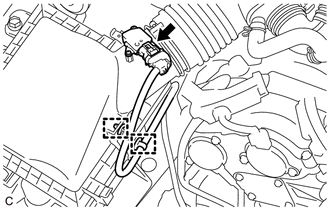
DISCONNECT NO. 1 FUEL VAPOR FEED HOSE
-
Slide the clip and disconnect the No. 1 fuel vapor feed hose from the purge valve (purge VSV).
-
-
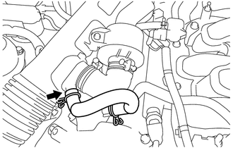
DISCONNECT NO. 1 RADIATOR HOSE
-
Slide the clip and disconnect the No. 1 radiator hose from the water inlet.
-
-
DISCONNECT NO. 2 RADIATOR HOSE SUB-ASSEMBLY
-
DISCONNECT INLET NO. 1 OIL COOLER HOSE (w/ Transmission Oil Cooler)
-
DISCONNECT OUTLET NO. 1 OIL COOLER HOSE (w/ Transmission Oil Cooler)
-
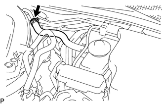
DISCONNECT INLET HEATER WATER HOSE A
-
Remove the water hose set.
-
Slide the clip and disconnect the inlet heater water hose A from the No. 2 water by-pass pipe.
-
-
DISCONNECT OUTLET HEATER WATER HOSE A
-
Remove the water hose set.
-
Slide the clip and disconnect the outlet heater water hose A from the No. 2 water by-pass pipe.
-
-
DISCONNECT NO. 1 COOLER REFRIGERANT DISCHARGE HOSE
-
DISCONNECT SUCTION HOSE
-
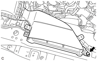
REMOVE ENGINE ROOM ECU COVER
-
DISCONNECT WIRE HARNESS (for LHD)
Tech Tips
After disconnecting the wire harness, secure it with tape or equivalent to keep it out of the way.
-
Engine room LH side:
-
Disconnect the 3 connectors from the No. 2 connector holder.
-
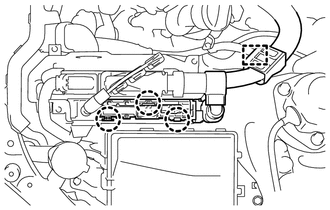
Disconnect the clamp.
-
Disengage the 3 claws and disconnect the No. 2 connector holder.
-
Disengage the lock, pull up the lever and disconnect the ECM connector.
-
-
Engine room RH side:
-
Disconnect the clamp.
-
Remove the nut and disconnect the No. 2 engine wire from the positive (+) battery terminal.
-
Remove the No. 1 engine room relay block cover from the No. 1 engine room relay block and No. 1 junction block assembly.
-
Disconnect the 2 No. 4 engine wire clamps.
-
Remove the nut from the No. 1 engine room relay block and No. 1 junction block assembly.
-
Disengage the 2 claws and disconnect the No. 4 engine wire from the No. 1 engine room relay block and No. 1 junction block assembly.
-
Disconnect the clamp.
-
Remove the bolt and disconnect the No. 3 engine wire from the body.
-
-
-
DISCONNECT WIRE HARNESS (for RHD)
Tech Tips
After disconnecting the wire harness, secure it with tape or equivalent to keep it out of the way.
-
Engine room LH side:
-
Disconnect the clamp.
-
Remove the nut and disconnect the No. 2 engine wire from the positive (+) battery terminal.
-
Remove the No. 1 engine room relay block cover from the No. 1 engine room relay block and No. 1 junction block assembly.
-
Disconnect the clamp.
-
Remove the nut from the No. 1 engine room relay block and No. 1 junction block assembly.
-
Disengage the 2 claws and disconnect the No. 4 engine wire from the No. 1 engine room relay block and No. 1 junction block assembly.
-
Disconnect the 3 connectors from the No. 2 connector holder.
-
Disconnect the clamp.
-
Disengage the 3 claws and disconnect the No. 2 connector holder.
-
Disengage the lock, pull up the lever and disconnect the ECM connector.
-
-
Engine room RH side:
-
Disconnect the clamp.
-
Remove the bolt and disconnect the No. 3 engine wire from the body.
-
-
-
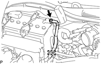
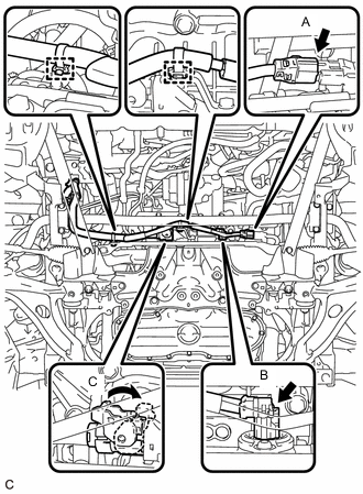
DISCONNECT FUEL TUBE SUB-ASSEMBLY (for LHD)
-
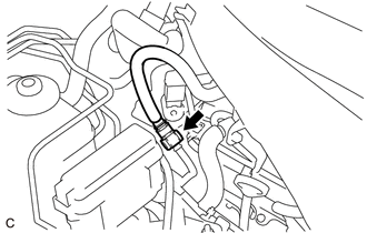
Remove the fuel pipe clamp.
-
Disconnect the fuel tube sub-assembly from the fuel pipe.
-
-
DISCONNECT FUEL TUBE SUB-ASSEMBLY (for RHD)
-
Remove the fuel pipe clamp.
-
Disconnect the fuel tube sub-assembly from the fuel pipe.
-
-
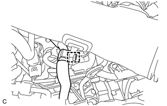
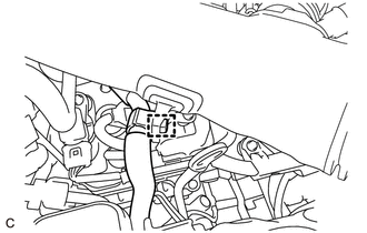
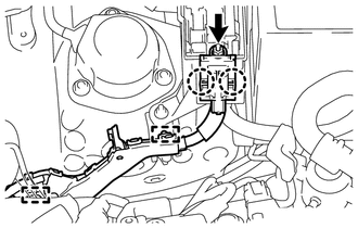
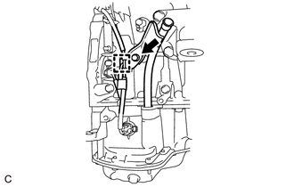
DISCONNECT NO. 2 FUEL TUBE SUB-ASSEMBLY
-
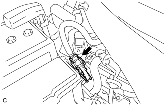
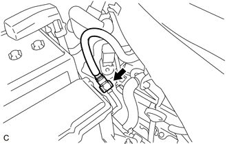
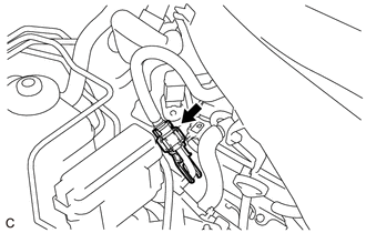
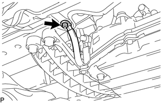
Remove the fuel pipe clamp as shown in the illustration.
-
Disconnect the No. 2 fuel tube sub-assembly from the fuel pipe.
-
-
REMOVE PROPELLER WITH CENTER BEARING SHAFT ASSEMBLY
-
REMOVE NO. 1 EXHAUST PIPE SUPPORT BRACKET SUB-ASSEMBLY
-
SEPARATE STEERING SLIDING WITH SHAFT YOKE SUB-ASSEMBLY
-
DISCONNECT FRONT SHOCK ABSORBER ASSEMBLY LH
-
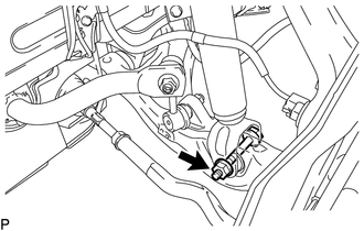
Remove the bolt and nut, and disconnect the front shock absorber assembly LH from the front suspension lower arm assembly LH.
Note
When removing the bolt, keep the nut from rotating.
-
-
DISCONNECT FRONT SHOCK ABSORBER ASSEMBLY RH
Tech Tips
Perform the same procedure as for the LH side.
-
SEPARATE FRONT LOWER BALL JOINT ASSEMBLY LH
-
SEPARATE FRONT LOWER BALL JOINT ASSEMBLY RH
Tech Tips
Perform the same procedure as for the LH side.
-
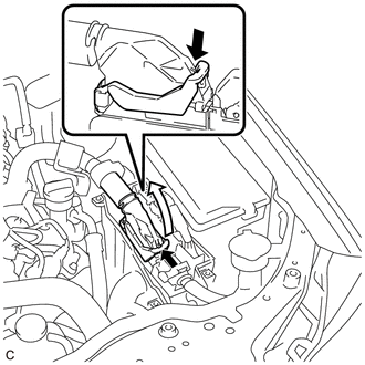
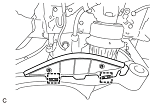
DISCONNECT WIRE HARNESS (for LHD)
-
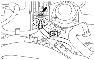
Disconnect the 2 wire harness clamps from the bracket.
-
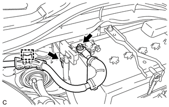
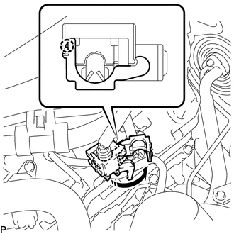
Disconnect the 2 connectors (A) and (B) from the power steering link assembly.
-
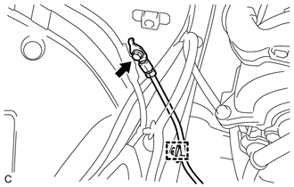
Release the lock of connector (C) and disconnect the connector from the power steering link assembly.
-
-
DISCONNECT WIRE HARNESS (for RHD)
-
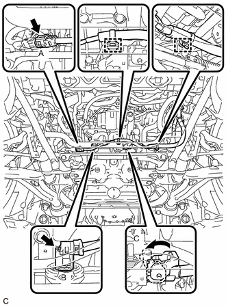
Disconnect the 2 wire harness clamps from the bracket.
-
Disconnect the 2 connectors (A) and (B) from the power steering link assembly.
-
Release the lock of connector (C) and disconnect the connector from the power steering link assembly.
-
-
REMOVE FLOOR SHIFT GEAR SHIFTING ROD SUB-ASSEMBLY
-
REMOVE SUSPENSION TOWER DAMPER
-
REMOVE FRONT UPPER NO. 2 SUSPENSION MEMBER
-
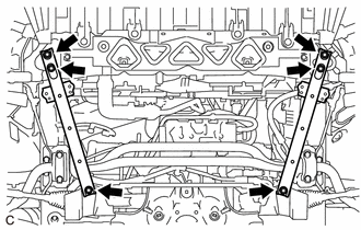
Remove the 6 bolts and 2 front upper No. 2 suspension members.
-
-
REMOVE FRONT LOWER SUSPENSION MEMBER PROTECTOR
-
Remove the 4 bolts and front lower suspension member protector from the front suspension crossmember sub-assembly.
-
-
REMOVE ENGINE ASSEMBLY WITH TRANSMISSION
-
Remove the nut and disconnect the No. 2 earth wire from the body.
-
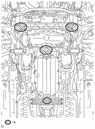
*a Attachment Installation Position Place height adjustment attachments and plate lift attachments in the positions shown in the illustration and set an engine lifter underneath the engine assembly with transmission.
Note
-
Using height adjustment attachments and plate lift attachments, place the engine assembly with transmission horizontally.
-
Securely support the engine assembly to prevent it from turning upside down until it is secured to an engine stand.
-
To prevent the oil pan from deforming, do not place any attachments under the oil pan of the engine assembly with transmission.
-
Do not perform any procedure while the engine assembly is suspended because doing so may cause the engine assembly to drop, resulting in injury. However, the engine assembly needs to be suspended when it is installed to or removed from an engine stand.
-
-
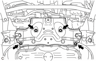
Remove the 4 bolts, and separate the rear engine mounting member from the body.
-
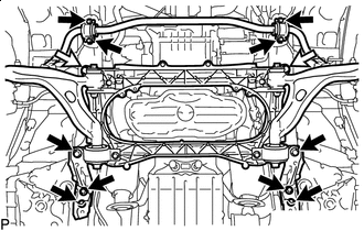
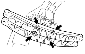
Bolt 
Nut Remove the 4 bolts and disconnect the front No. 2 stabilizer bracket LH and front No. 2 stabilizer bracket RH.
-
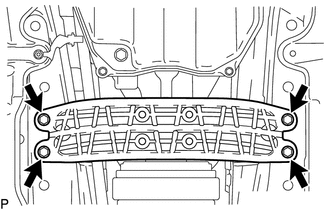
Remove the 6 bolts, 2 nuts and strut bar bracket reinforcement LH, strut bar bracket reinforcement RH and front suspension crossmember sub-assembly.
-
Operate the engine lifter, then remove the engine assembly with transmission from the vehicle.
Note
-
Make sure that the engine assembly with transmission is clear of all the wiring, hoses and steering sliding with shaft yoke sub-assembly.
-
After removing the engine assembly with transmission, hang the steering sliding with shaft yoke sub-assembly with rope or equivalent.
-
-
-
INSTALL ENGINE HANGERS
-
*a No. 1 Engine Hanger *b No. 2 Engine Hanger Install the No. 1 engine hanger and No. 2 engine hanger with the 4 bolts as shown in the illustration.
- Torque:
- 33 N*m { 337 kgf*cm, 24 ft.*lbf }
Tech Tips
No. 1 Engine Hanger 12281 - 31070 No. 2 Engine Hanger 12282 - 31160 Bolt 91671-10825 -
Attach an engine sling device and hang the engine assembly with a chain block.
Note
-
Pay attention to the angle of the sling device as the engine assembly or No. 1 engine hanger and No. 2 engine hanger may be damaged or deformed if the angle is incorrect.
-
Do not perform any procedure while the engine assembly is suspended because doing so may cause the engine assembly to drop, resulting in injury. However, the engine assembly needs to be suspended when it is installed to or removed from an engine stand.
-
-
-
REMOVE NO. 2 ENGINE OIL LEVEL DIPSTICK GUIDE
-
REMOVE ENGINE OIL LEVEL DIPSTICK GUIDE
-
Disconnect the clamp from the engine oil level dipstick guide.
-
Remove the bolt and engine oil level dipstick guide.
-
Remove the O-ring from the engine oil level dipstick guide.
-
-
REMOVE ENGINE UNDER COVER SUB-ASSEMBLY LH
-
Remove the 2 clamps and engine under cover sub-assembly LH.
-
-
REMOVE ENGINE UNDER COVER SUB-ASSEMBLY RH
-
Remove the 2 clamps and engine under cover sub-assembly RH.
-
-
REMOVE EXHAUST MANIFOLD SUB-ASSEMBLY LH (TWC: Front Catalyst)
-
REMOVE EXHAUST MANIFOLD SUB-ASSEMBLY RH (TWC: Front Catalyst)
-
REMOVE STARTER COVER
-
REMOVE STARTER ASSEMBLY
-
REMOVE FLYWHEEL HOUSING SIDE COVER
-
REMOVE DRIVE PLATE AND TORQUE CONVERTER SETTING BOLT
-
REMOVE AUTOMATIC TRANSMISSION ASSEMBLY
-
REMOVE DRIVE PLATE AND RING GEAR SUB-ASSEMBLY
-
REMOVE FRONT SUSPENSION CROSSMEMBER SUB-ASSEMBLY
-
*a LH Side *b RH Side Remove the 2 bolts and front suspension crossmember sub-assembly from the engine assembly.
-
-
REMOVE FRONT ENGINE MOUNTING INSULATOR
Tech Tips
Perform this procedure only when replacement of the front engine mounting insulator is necessary.
-
*a LH Side *b RH Side Remove the 2 nuts and 2 front engine mounting insulators from the front suspension crossmember sub-assembly.
-
-
REMOVE REAR ENGINE MOUNTING MEMBER
Tech Tips
Perform this procedure only when replacement of the rear engine mounting insulator is necessary.
-
Remove the 4 nuts and rear engine mounting member from the rear engine mounting insulator.
-
-
REMOVE REAR ENGINE MOUNTING INSULATOR
Tech Tips
Perform this procedure only when replacement of the rear engine mounting insulator is necessary.
-
Remove the 4 nuts and rear engine mounting insulator from the rear engine mounting bracket.
-
-
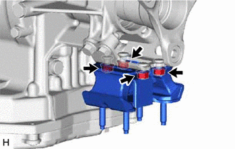
REMOVE REAR ENGINE MOUNTING BRACKET
Tech Tips
Perform this procedure only when replacement of the rear engine mounting insulator is necessary.
-
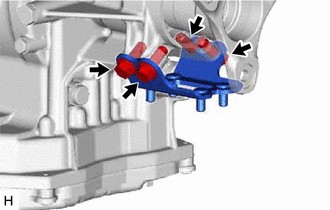
Remove the 4 bolts and rear engine mounting bracket from the automatic transmission assembly.
-
-
INSTALL ENGINE ASSEMBLY TO ENGINE STAND
-
Install the engine assembly to an engine stand.
Note
-
Pay attention to the angle of the sling device as the engine assembly or No. 1 engine hangers may be damaged or deformed if the angle is incorrect.
-
Do not perform any procedure while the engine assembly is suspended because doing so may cause the engine assembly to drop, resulting in injury. However, the engine assembly needs to be suspended when it is installed to or removed from an engine stand.
-
-
Remove the 4 bolts, No. 1 engine hanger and No. 2 engine hanger.
-