CYLINDER BLOCK DISASSEMBLY

PROCEDURE
-
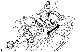
INSPECT CONNECTING ROD THRUST CLEARANCE
-
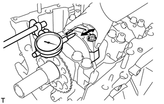
Using a dial indicator, measure the connecting rod thrust clearance while moving the connecting rod sub-assembly back and forth.
Standard thrust clearance 0.25 to 0.40 mm (0.00984 to 0.0158 in.) Maximum thrust clearance 0.50 mm (0.0197 in.) If the thrust clearance is more than the maximum, replace the connecting rod sub-assemblies as necessary. If necessary, replace the crankshaft.
-
-
INSPECT CONNECTING ROD OIL CLEARANCE
-
Check that the matchmarks on the connecting rod sub-assembly and connecting rod cap are aligned.
Tech Tips
The matchmarks on the connecting rod sub-assembly and connecting rod cap are guides for correct reassembly.
-
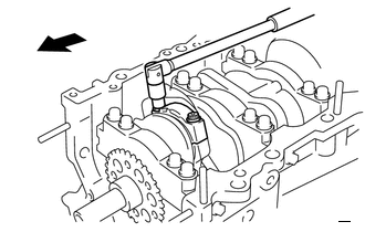

Engine Front Remove the 2 connecting rod bolts.
-
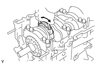
Using the 2 removed connecting rod bolts, remove the connecting rod cap and lower bearing by wiggling the connecting rod cap right and left.
Tech Tips
Keep the lower bearing inserted to the connecting rod cap.
-
Clean the crank pin and connecting rod bearing.
-
Check the crank pin and connecting rod bearing for pitting and scratches.
-
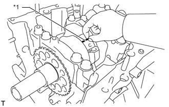
*1 Plastigage Lay a strip of Plastigage on the crank pin.
-
*1 Front Mark Engine Front Check that the front mark of the connecting rod cap is facing forward.
-
Apply a light coat of engine oil to the threads and under the heads of the connecting rod bolts.
-
Install the connecting rod cap.
Note
Do not turn the crankshaft.
Tech Tips
The connecting rod bolts are tightened in 2 progressive steps.
-
Step 1
-
Install and alternately tighten the connecting rod bolts of each connecting rod cap in several steps.
- Torque:
- 24.5 N*m { 250 kgf*cm, 18 ft.*lbf }
-
-
Step 2
-
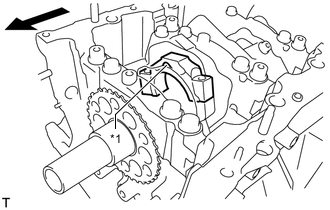
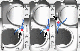
Mark the front side of each connecting rod bolt with paint.
-
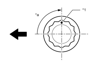
*1 Front Mark *a 90° Engine Front Tighten the connecting rod bolts 90°.
-
-
Check that the paint marks are now at a 90° angle to the front.
-
Remove the 2 connecting rod bolts and connecting rod cap.
-
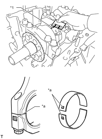
*1 Plastigage *a 1, 2, 3 or 4 Mark Measure the Plastigage at its widest point.
Standard oil clearance 0.026 to 0.046 mm (0.00102 to 0.00181 in.) Maximum oil clearance 0.070 mm (0.00276 in.) If the oil clearance is more than the maximum, replace the connecting rod bearings. If necessary, inspect the crankshaft.
Tech Tips
If replacing a connecting rod bearing, replace it with one that has the same number as its respective connecting rod cap.
Each bearing standard thickness is indicated by a number (1, 2, 3 or 4) marked on its surface.
Standard Connecting Rod Diameter Mark Specified Condition 1 51.000 to 51.006 mm
(2.00787 to 2.00811 in.)
2 51.007 to 51.012 mm
(2.00815 to 2.00834 in.)
3 51.013 to 51.018 mm
(2.00838 to 2.00858 in.)
4 51.019 to 51.024 mm
(2.00862 to 2.00881 in.)
Standard Connecting Rod Bearing Center Wall Thickness Mark Specified Condition 1 1.484 to 1.487 mm
(0.05843 to 0.05854 in.)
2 1.487 to 1.490 mm
(0.05854 to 0.05866 in.)
3 1.490 to 1.493 mm
(0.05866 to 0.05878 in.)
4 1.493 to 1.496 mm
(0.05878 to 0.05890 in.)
Standard crankshaft pin diameter 47.992 to 48.000 mm (1.8894 to 1.8898 in.) Note
Completely remove the Plastigage after the measurement.
-
-
REMOVE PISTON SUB-ASSEMBLY WITH CONNECTING ROD
-
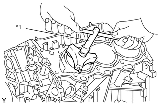
*1 Ridge Reamer Using a ridge reamer, remove all the carbon from the top of the cylinder.
-
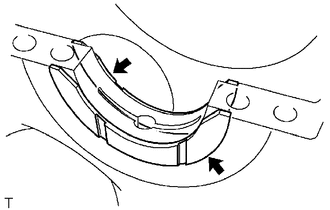
Push the piston, connecting rod sub-assembly and upper connecting rod bearing through the top of the cylinder block sub-assembly.
Tech Tips
-
Keep the connecting rod bearing, connecting rod sub-assembly and connecting rod cap together.
-
Arrange the piston and connecting rod assemblies in the correct order.
-
-
-
REMOVE CONNECTING ROD BEARING
-
Remove the connecting rod bearings from the connecting rod sub-assemblies and connecting rod caps.
Tech Tips
Arrange the removed parts in the correct order.
-
-
INSPECT CRANKSHAFT THRUST CLEARANCE
-
Using a dial indicator, measure the thrust clearance while prying the crankshaft back and forth with a screwdriver.
Standard thrust clearance 0.04 to 0.24 mm (0.00157 to 0.00945 in.) Maximum thrust clearance 0.30 mm (0.0118 in.) If the thrust clearance is more than the maximum, replace the thrust washers as a set. If necessary, replace the crankshaft.
Thrust washer thickness 2.43 to 2.48 mm (0.0957 to 0.0976 in.)
-
-
REMOVE CRANKSHAFT
-
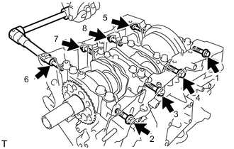
Uniformly loosen and remove the 8 bolts and 8 seal washers in several steps and in the sequence shown in the illustration.
-
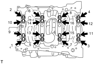
Uniformly loosen and remove the 16 crankshaft bearing cap set bolts in several steps and in the sequence shown in the illustration.
-
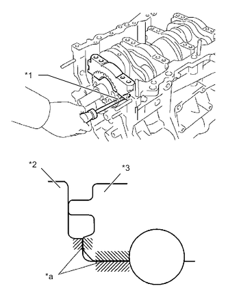
*1 Protective Tape *2 Cylinder Block *3 Crankshaft Bearing Cap *a Joint Surface Using a screwdriver, pry out the crankshaft bearing caps. Remove the 4 crankshaft bearing caps and lower crankshaft bearings.
Note
-
Push up on the crankshaft bearing cap slowly and evenly, alternating from the right and left side so that the crankshaft bearing cap can be removed.
-
Be careful not to damage the joint surfaces of the cylinder block and the crankshaft bearing cap.
Tech Tips
-
Tape the screwdriver tip before use.
-
Arrange the removed parts in the correct order.
-
-
Remove the crankshaft.
-
-
REMOVE CRANKSHAFT BEARING
-
Remove the upper crankshaft bearings and lower crankshaft bearings.
Tech Tips
Arrange the removed parts in the correct order.
-
-
REMOVE CRANKSHAFT THRUST WASHER SET
-
Remove the crankshaft thrust washer set from the cylinder block.
-
-
REMOVE PISTON RING SET
-
*1 Piston Ring Expander Using a piston ring expander, remove the No. 1 compression ring, No. 2 compression ring and oil ring.
-
Remove the oil ring expander by hand.
Tech Tips
Arrange the removed parts in the correct order.
-
-
REMOVE PISTON SUB-ASSEMBLY WITH PIN
-
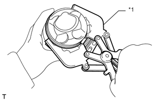
Disconnect the connecting rod from the piston.
-
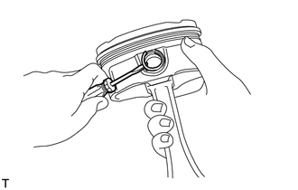
Using a screwdriver, pry off the piston pin hole snap rings from the piston.
-
Gradually heat the piston to approximately 80°C (176°F).
CAUTION:
Be sure to wear protective gloves.
-
Using a brass bar and a plastic-faced hammer, lightly tap out the piston pin and remove the connecting rod sub-assembly.
Tech Tips
-
The piston and piston pin are a matched set.
-
Arrange the pistons, piston pins, connecting rod sub-assemblies and connecting rod bearings in the correct order.
-
-
-
Using a gasket scraper, remove the carbon from the piston top.
-
Using a groove cleaning tool or broken ring, clean the piston ring grooves.
-
Using solvent and a brush, thoroughly clean the piston.
Note
Do not use a wire brush.
-
-
REMOVE NO. 1 OIL NOZZLE SUB-ASSEMBLY
-
Using a 5 mm hexagon wrench, remove the 3 bolts and 3 No. 1 oil nozzle sub-assemblies.
-
Check the 3 No. 1 oil nozzle sub-assemblies for damage or clogging.
If necessary, replace the No. 1 oil nozzle sub-assembly.
-
-
REMOVE CONNECTING ROD SMALL END BUSH
-
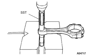
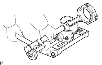
Using SST and press, press out the connecting rod small end bush.
- SST
- 09222-30010
-