ENGINE UNIT DISASSEMBLY

PROCEDURE
-
REMOVE NO. 2 FUEL DELIVERY PIPE SUB-ASSEMBLY
-
REMOVE FUEL DELIVERY PIPE SUB-ASSEMBLY
-
REMOVE FUEL INJECTOR ASSEMBLY
-
REMOVE FUEL INJECTOR SEAL
-
REMOVE OIL FILLER CAP SUB-ASSEMBLY
-
Remove the oil filler cap sub-assembly and gasket.
-
-
REMOVE RADIATOR CAP SUB-ASSEMBLY
-
Remove the radiator cap sub-assembly.
-
-
REMOVE SPARK PLUG
-
REMOVE OIL PAN DRAIN PLUG
-
Remove the oil pan drain plug and gasket.
-
-
REMOVE PCV VALVE (VENTILATION VALVE SUB-ASSEMBLY)
-
REMOVE VVT SENSOR (for Intake Side of Bank 1)
-
REMOVE VVT SENSOR (for Exhaust Side of Bank 1)
-
REMOVE VVT SENSOR (for Intake Side of Bank 2)
-
REMOVE VVT SENSOR (for Exhaust Side of Bank 2)
-
REMOVE CAMSHAFT TIMING OIL CONTROL VALVE ASSEMBLY (for Exhaust Side of Bank 1)
-
REMOVE CAMSHAFT TIMING OIL CONTROL VALVE ASSEMBLY (for Intake Side of Bank 1)
-
REMOVE CAMSHAFT TIMING OIL CONTROL VALVE ASSEMBLY (for Intake Side of Bank 2)
-
REMOVE CAMSHAFT TIMING OIL CONTROL VALVE ASSEMBLY (for Exhaust Side of Bank 2)
-
REMOVE ENGINE OIL LEVEL SENSOR
-
REMOVE ENGINE COOLANT TEMPERATURE SENSOR
-
REMOVE CRANKSHAFT POSITION SENSOR
-
REMOVE NO. 1 OIL PIPE
-
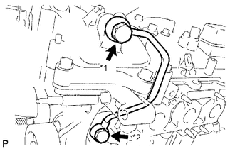
*1 Oil Pipe Union *2 Oil Check Valve Bolt Remove the oil check valve bolt, oil pipe union, 3 gaskets and No. 1 oil pipe.
-
Remove the oil control valve filter LH .
Note
Do not touch the mesh when removing the oil control valve filter LH.
-
-
REMOVE NO. 2 OIL PIPE
-
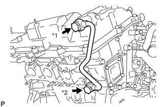
*1 Oil Pipe Union *2 Oil Check Valve Bolt Remove the oil check valve bolt, oil pipe union, 3 gaskets and No. 2 oil pipe.
-
Remove the oil control valve filter RH.
Note
Do not touch the mesh when removing the oil control valve filter RH.
-
-
REMOVE CYLINDER BLOCK WATER DRAIN COCK SUB-ASSEMBLY
-
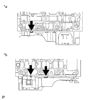
Remove the 2 water drain cock plugs from the 2 cylinder block water drain cock sub-assemblies.
-
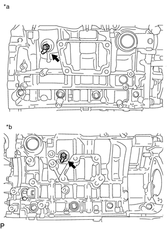
*a for Bank 1 *b for Bank 2 Remove the 2 cylinder block water drain cock sub-assemblies from the cylinder block sub-assembly.
-
-
REMOVE ENGINE OIL PRESSURE SWITCH ASSEMBLY
-
REMOVE OIL FILTER CAP ASSEMBLY
-
REMOVE CRANKSHAFT PULLEY
-
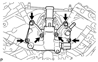
REMOVE WATER INLET
-
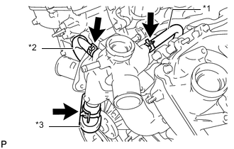
*1 No. 4 Water By-pass Hose *2 No. 6 Water By-pass Hose *3 No. 3 Water By-pass Hose Disconnect the No. 3, No. 4 and No. 6 water by-pass hoses.
-
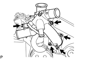
Remove the 4 bolts, nut and water inlet.
-
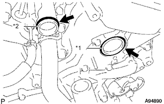
*1 No. 1 Water Inlet Housing Gasket *2 Water Outlet Pipe O-ring Remove the No. 1 water inlet housing gasket and water outlet pipe O-ring.
-
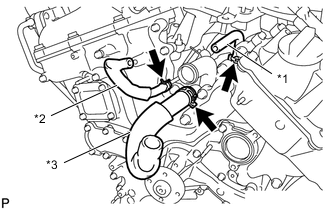
*1 No. 4 Water By-pass Hose *2 No. 6 Water By-pass Hose *3 No. 3 Water By-pass Hose Remove the No. 3, No. 4 and No. 6 water by-pass hoses.
-
-
REMOVE WATER INLET SUB-ASSEMBLY WITH THERMOSTAT
-
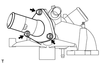
Remove the 3 nuts and water inlet sub-assembly with thermostat.
-
Remove the water inlet housing gasket from the water inlet.
-
-
REMOVE REAR WATER BY-PASS JOINT
-
Remove the 2 bolts, 4 nuts and rear water by-pass joint.
-
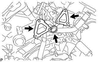
Remove the 2 water outlet gaskets and water outlet pipe O-ring.
-
-
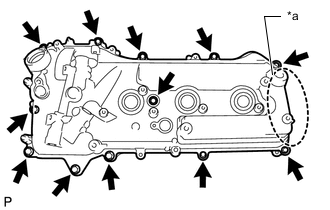
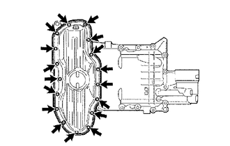
REMOVE CYLINDER HEAD COVER SUB-ASSEMBLY
-
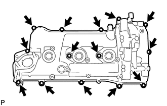
Remove the 14 bolts, 2 cylinder head cover seal washers, cylinder head cover sub-assembly and cylinder head cover gasket.
-
Remove the 3 gaskets.
-
-
REMOVE CYLINDER HEAD COVER SUB-ASSEMBLY LH
-
*a Be careful of baffle plate Remove the 12 bolts, cylinder head cover seal washer, cylinder head cover sub-assembly LH and cylinder head cover gasket LH.
Note
The baffle plate is located on the back of the portion shown in the illustration.
Do not damage the baffle plate when removing the cylinder head cover sub-assembly LH.
-
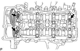
Remove the 3 gaskets.
-
-
REMOVE SPARK PLUG TUBE GASKET
-
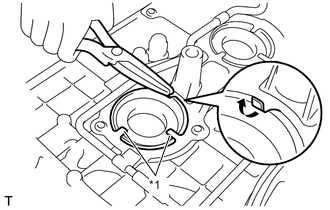
*1 Claw Pry up the claws of the ventilation baffle plate.
Note
Do not deform the claws of the ventilation baffle plate more than necessary.
-
Remove the 6 spark plug tube gaskets from the cylinder head cover sub-assemblies.
Note
-
As much as possible prevent the spark plug tube gaskets from being deformed. The removed spark plug tube gaskets will be used when reinstalling new spark plug tube gaskets.
-
Do not damage the cylinder head cover sub-assemblies.
-
-
-
REMOVE NO. 2 OIL PAN SUB-ASSEMBLY
-
Remove the 15 bolts and 2 nuts.
-
*1 Oil Pan Seal Cutter Insert the blade of an oil pan seal cutter between the oil pan sub-assembly and No. 2 oil pan sub-assembly. Cut through the applied sealer and remove the No. 2 oil pan sub-assembly.
Note
Be careful not to damage the contact surfaces of the oil pan sub-assembly and No. 2 oil pan sub-assembly.
-
-
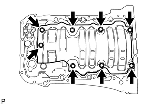
REMOVE OIL PAN SUB-ASSEMBLY
-
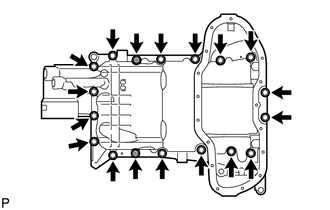
Remove the 16 bolts and 2 nuts.
Tech Tips
-
Be sure to clean the bolts and stud bolts and check the threads for cracks or other damage.
-
Arrange the removed parts in the correct order.
-
-
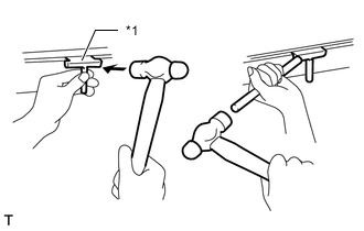
*a LH Side *b RH Side Remove the oil pan sub-assembly by prying between the oil pan sub-assembly and cylinder block sub-assembly with a screwdriver.
Note
Be careful not to damage the contact surfaces of the cylinder block sub-assembly and oil pan sub-assembly.
Tech Tips
Tape the screwdriver tip before use.
-
Remove the 2 O-rings.
-
-
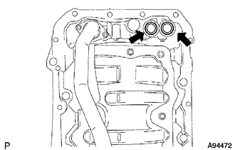
REMOVE OIL STRAINER SUB-ASSEMBLY
-
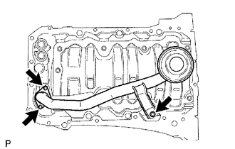
Remove the 3 nuts, oil strainer sub-assembly and oil strainer gasket.
-
-
REMOVE NO. 1 OIL PAN BAFFLE PLATE
-
Remove the 8 bolts and No. 1 oil pan baffle plate.
-
-
REMOVE ENGINE REAR OIL SEAL RETAINER
-
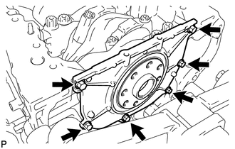
Remove the 6 bolts.
-
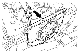
*1 Protective tape Using a screwdriver, pry out the engine rear oil seal retainer.
Note
Be careful not to damage the engine rear oil seal retainer and cylinder block sub-assembly.
Tech Tips
Tape the screwdriver tip before use.
-
-
REMOVE ENGINE REAR OIL SEAL
-

*1 Wooden Block *2 Protective Tape Place the engine rear oil seal retainer on wooden blocks.
Note
Be careful not to damage the engine rear oil seal retainer.
-
Using a screwdriver and a hammer, tap out the engine rear oil seal.
Tech Tips
Tape the screwdriver tip before use.
-
-
REMOVE TIMING CHAIN COVER PLATE
-
REMOVE ENGINE WATER PUMP ASSEMBLY
-
REMOVE TIMING CHAIN OR BELT COVER SUB-ASSEMBLY
-
REMOVE TIMING GEAR CASE OR TIMING CHAIN CASE OIL SEAL
-
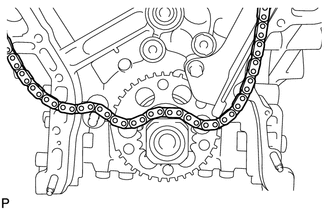
SET NO. 1 CYLINDER TO TDC / COMPRESSION
-
Temporarily tighten the crankshaft pulley set bolt.
-
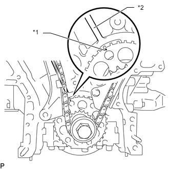
*1 Timing Mark *2 Bank 1 Cylinder Block Center Line Set the timing mark on the crank angle sensor plate to the bank 1 cylinder block bore center line (TDC/compression).
-
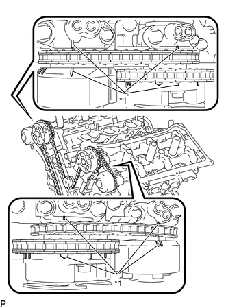
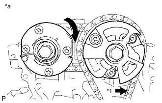
*1 Timing Mark Check that the timing marks of the camshaft timing gears are aligned with the timing marks of the camshaft bearing caps as shown in the illustration.
If not, turn the crankshaft 1 revolution (360°) and align the timing marks as above.
-
-
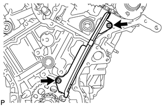
REMOVE NO. 1 CHAIN TENSIONER ASSEMBLY
-
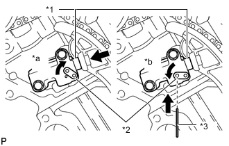
*1 Plunger *2 Stopper Plate *3 Hexagon Wrench *a Move Stopper Plate Upward *b Move Stopper Plate Downward Move the stopper plate upward to release the lock, and push the plunger deep into the No. 1 chain tensioner assembly.
-
Move the stopper plate downward to set the lock, and insert a hexagon wrench into the hole of the stopper plate.
-
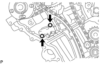
Remove the 2 bolts and No. 1 chain tensioner assembly.
-
-
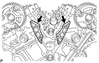
REMOVE CHAIN TENSIONER SLIPPER
-
Remove the chain tensioner slipper.
-
-
REMOVE CHAIN SUB-ASSEMBLY
-
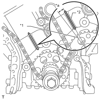
*1 Timing Mark *2 Bank 1 Cylinder Block Center Line *a 10° Turn the crankshaft counterclockwise 10° to loosen the chain sub-assembly around the crankshaft timing gear or sprocket.
-
Remove the crankshaft pulley set bolt.
-
Remove the chain sub-assembly from the crankshaft timing gear or sprocket and place it on the crankshaft.
-
*1 Chain Sub-assembly between Banks *a for Bank 1 Turn the camshaft timing gear assembly on bank 1 clockwise (approximately 60°) and set it as shown in the illustration.
Be sure to loosen the chain sub-assembly between the banks.
CAUTION:
As the camshafts turn suddenly, do not touch the camshafts or camshaft timing gears.
-
Remove the chain sub-assembly.
-
-
REMOVE IDLE SPROCKET ASSEMBLY
-
Using a 10 mm hexagon wrench, remove the No. 2 idle gear shaft, idle sprocket assembly and No. 1 idle gear shaft.
-
-
REMOVE NO. 1 CHAIN VIBRATION DAMPER
-
Remove the 2 bolts and No. 1 chain vibration damper.
-
-
REMOVE NO. 2 CHAIN VIBRATION DAMPER
-
Remove the 2 No. 2 chain vibration dampers.
-
-
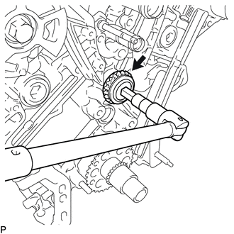
REMOVE CRANKSHAFT TIMING GEAR OR SPROCKET
-
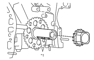
*1 Crankshaft Timing Gear Key Remove the crankshaft timeng gear or sprocket from the crankshaft.
Note
Be careful not to drop the crankshaft timing gear keys.
-
-
REMOVE CRANKSHAFT TIMING GEAR KEY
-
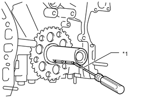
*1 Protective Tape Remove the 2 crankshaft timing gear keys from the crankshaft.
Tech Tips
Tape the screwdriver tip before use.
-
-
REMOVE CAMSHAFT TIMING GEARS AND NO. 2 CHAIN (for Bank 1)
-
REMOVE NO. 2 CHAIN TENSIONER ASSEMBLY
-
REMOVE CAMSHAFT BEARING CAP (for Bank 1)
-
REMOVE CAMSHAFT
-
REMOVE NO. 2 CAMSHAFT
-
REMOVE CAMSHAFT HOUSING SUB-ASSEMBLY RH
-
REMOVE CAMSHAFT TIMING GEARS AND NO. 2 CHAIN (for Bank 2)
-
REMOVE NO. 3 CHAIN TENSIONER ASSEMBLY
-
REMOVE CAMSHAFT BEARING CAP (for Bank 2)
-
REMOVE NO. 3 CAMSHAFT SUB-ASSEMBLY
-
REMOVE NO. 4 CAMSHAFT SUB-ASSEMBLY
-
REMOVE CAMSHAFT HOUSING SUB-ASSEMBLY LH
-
REMOVE NO. 1 VALVE ROCKER ARM SUB-ASSEMBLY
-
REMOVE VALVE LASH ADJUSTER ASSEMBLY
-
REMOVE VALVE STEM CAP
-
REMOVE CYLINDER HEAD SUB-ASSEMBLY
-
REMOVE CYLINDER HEAD GASKET
-
REMOVE CYLINDER HEAD LH
-
REMOVE NO. 2 CYLINDER HEAD GASKET
-
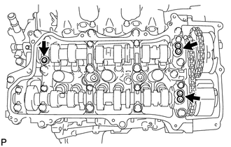
REMOVE NO. 5 ENGINE WIRE
-
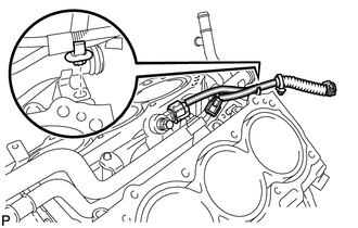
Detach the clamp and remove the No. 5 engine wire.
-
-
REMOVE KNOCK CONTROL SENSOR
-
REMOVE CYLINDER BLOCK WATER JACKET SPACER RH
-
Using needle-nose pliers, remove the cylinder block water jacket spacer RH.
Note
Be sure to remove the cylinder block water jacket spacer RH if turning the cylinder block sub-assembly.
-
-
REMOVE CYLINDER BLOCK WATER JACKET SPACER LH
-
Using needle-nose pliers, remove the cylinder block water jacket spacer LH.
Note
Be sure to remove the cylinder block water jacket spacer LH if turning the cylinder block sub-assembly.
-
-
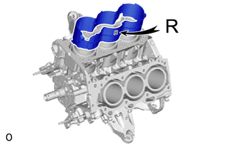
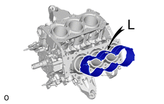
REMOVE WATER OUTLET PIPE SUB-ASSEMBLY
-
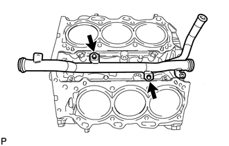
Remove the 2 bolts and water outlet pipe sub-assembly.
-
-
REMOVE NO. 1 STRAIGHT PIN
Note
It is not necessary to remove a straight pin unless it is being replaced.
-
REMOVE RING WITH HEAD PIN
Note
It is not necessary to remove a ring with head pin unless it is being replaced.
-
REMOVE STUD BOLT
Note
If a stud bolt is deformed or its threads are damaged, replace it.