ENGINE UNIT REASSEMBLY

PROCEDURE
-
INSTALL STUD BOLT
Note
If a stud bolt is deformed or its threads are damaged, replace it.
-
Using an E6 "TORX" socket wrench, install the stud bolts as shown in the illustration.
- Torque:
- for stud bolt A
- 4.0 N*m { 41 kgf*cm, 35 in.*lbf }
- for stud bolt B
- 4.4 N*m { 45 kgf*cm, 39 in.*lbf }
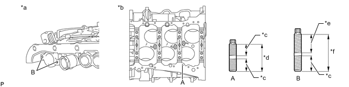
*a Timing Chain Or Belt Cover Sub-assembly Lower *b Cylinder Block Sub-assembly Lower *c 9.0 mm (0.354 in.) *d 19 mm (0.748 in.) *e 16 mm (0.630 in.) *f 27 mm (1.06 in.) -
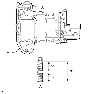
*a 9.0 mm (0.354 in.) *b 19 mm (0.748 in.) Using an E6 "TORX" socket wrench, install the stud bolts as shown in the illustration.
- Torque:
- 4.0 N*m { 41 kgf*cm, 35 in.*lbf }
-
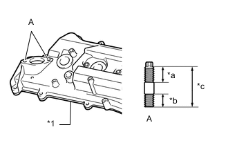
*1
Cylinder Head Cover Sub-assembly *a 19 mm (0.748 in.) *b 16 mm (0.630 in.) *c 44 mm (1.73 in.) Using an E8 "TORX" socket wrench, install the stud bolts as shown in the illustration.
- Torque:
- 10 N*m { 102 kgf*cm, 7 ft.*lbf }
-
-
INSTALL RING WITH HEAD PIN
Note
It is not necessary to remove a ring with head pin unless it is being replaced.
-
Using a plastic-faced hammer, tap in new ring with head pins to the camshaft housing sub-assembly.
Standard protrusion height 2.7 to 3.3 mm (0.106 to 0.130 in.) 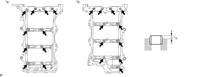
*a for Bank 2 *b for Bank 1 *c Protrusion Height - -
-
-
INSTALL NO. 1 STRAIGHT PIN
Note
It is not necessary to remove a No. 1 straight pin unless it is being replaced.
-
Using a plastic-faced hammer, tap in new No. 1 straight pins to the camshaft housing sub-assemblies.
Standard Protrusion Height Item Specified Condition Straight pin A 7.7 to 8.3 mm (0.303 to 0.327 in.) Straight pin B 5.7 to 6.3 mm (0.224 to 0.248 in.) 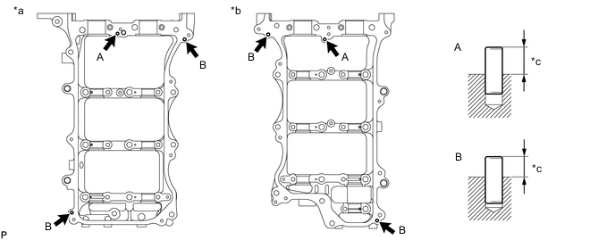
*a for Bank 2 *b for Bank 1 *c Protrusion Height - -
-
-
INSTALL ENGINE REAR OIL SEAL
-
Place the engine rear oil seal retainer on wooden blocks.
-
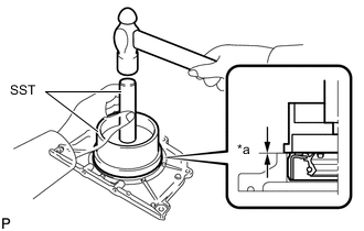
*a Standard depth Using SST, tap in a new engine rear oil seal until its surface is flush with the engine rear oil seal retainer edge.
- SST
- 09223-15030 ( 09951-07100 )
Standard depth -0.5 to 0.5 mm (-0.0197 to 0.0197 in.) Note
-
Keep the lip free of foreign matter.
-
Do not tap in the engine rear oil seal at an angle.
-
Do not tap in the engine rear oil seal more than necessary.
-
Do not deform the engine rear oil seal.
-
-
INSTALL ENGINE REAR OIL SEAL RETAINER
-
Apply MP grease to the lip of the engine rear oil seal.
-
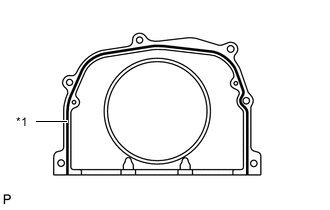
*1 Seal Packing Apply seal packing in a continuous line as shown in the illustration.
Seal packing Toyota Genuine Seal Packing Black, Three Bond 1207B or equivalent Seal diameter 2.0 to 3.0 mm (0.0787 to 0.118 in.) Note
-
Remove any oil from the contact surface.
-
Install the engine rear oil seal retainer within 3 minutes and tighten the bolts within 15 minutes after applying seal packing.
-
-
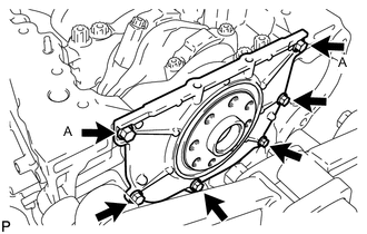
Apply adhesive 1324 to the 2 bolts A.
Note
Tighten the bolts within 3 minute after applying adhesive.
Adhesive Toyota Genuine Adhesive 1324, Three Bond 1324 or equivalent -
Install the engine rear oil seal retainer with the 6 bolts.
- Torque:
- 10 N*m { 102 kgf*cm, 7 ft.*lbf }
Note
-
Thoroughly wipe clean any seal packing.
-
Do not add engine oil for at least 2 hours after installation.
-
Do not start the engine for at least 2 hours after installation.
-
-
INSTALL WATER OUTLET PIPE SUB-ASSEMBLY
-
Install the water outlet pipe sub-assembly with the 2 bolts.
- Torque:
- 10 N*m { 102 kgf*cm, 7 ft.*lbf }
-
-
INSTALL CYLINDER BLOCK WATER JACKET SPACER RH
-
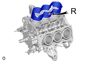
Install the cylinder block water jacket spacer RH as shown in the illustration.
-
-
INSTALL CYLINDER BLOCK WATER JACKET SPACER LH
-
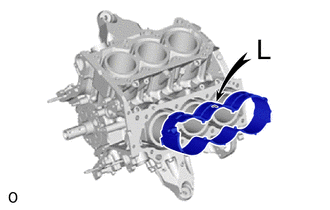
Install the cylinder block water jacket spacer LH as shown in the illustration.
-
-
INSTALL KNOCK CONTROL SENSOR
-
INSTALL NO. 5 ENGINE WIRE
-
Install the No. 5 engine wire with the clamp.
-
-
INSTALL CYLINDER HEAD GASKET
-
INSTALL CYLINDER HEAD SUB-ASSEMBLY
-
INSTALL NO. 2 CYLINDER HEAD GASKET
-
INSTALL CYLINDER HEAD LH
-
INSTALL VALVE STEM CAP
-
INSTALL VALVE LASH ADJUSTER ASSEMBLY
-
INSTALL NO. 1 VALVE ROCKER ARM SUB-ASSEMBLY
-
INSTALL NO. 3 CAMSHAFT SUB-ASSEMBLY
-
INSTALL NO. 4 CAMSHAFT SUB-ASSEMBLY
-
INSTALL CAMSHAFT BEARING CAP (for Bank 2)
-
INSTALL CAMSHAFT HOUSING SUB-ASSEMBLY LH
-
INSTALL CAMSHAFT
-
INSTALL NO. 2 CAMSHAFT
-
INSTALL CAMSHAFT BEARING CAP (for Bank 1)
-
INSTALL CAMSHAFT HOUSING SUB-ASSEMBLY RH
-
INSTALL NO. 2 CHAIN TENSIONER ASSEMBLY
-
INSTALL CAMSHAFT TIMING GEARS AND NO. 2 CHAIN (for Bank 1)
-
INSTALL NO. 3 CHAIN TENSIONER ASSEMBLY
-
INSTALL CAMSHAFT TIMING GEARS AND NO. 2 CHAIN (for Bank 2)
-
INSTALL NO. 1 CHAIN VIBRATION DAMPER
-
Install the No. 1 chain vibration damper with the 2 bolts.
- Torque:
- 22.5 N*m { 229 kgf*cm, 17 ft.*lbf }
-
-
INSTALL NO. 2 CHAIN VIBRATION DAMPER
-
Install the 2 No. 2 chain vibration dampers.
-
-
INSTALL CRANKSHAFT TIMING GEAR KEY
-
Install the 2 crankshaft timing gear keys to the crankshaft.
-
-
INSTALL CRANKSHAFT TIMING GEAR OR SPROCKET
-
Install the crankshaft timeng gear or sprocket to the crankshaft.
-
-
INSTALL IDLE SPROCKET ASSEMBLY
-
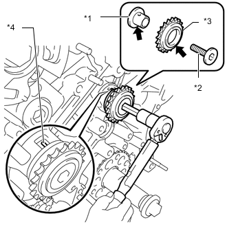
*1 No. 1 Idle Gear Shaft *2 No. 2 Idle Gear Shaft *3 Idle Sprocket Assembly *4 Knock Pin 
Apply Engine Oil Apply a light coat of engine oil to the rotating surface of the No. 1 idle gear shaft.
-
Temporarily install the No. 1 idle gear shaft and idle sprocket assembly with the No. 2 idle gear shaft while aligning the knock pin of the No. 1 idle gear with the knock pin groove of the cylinder block sub-assembly.
Note
Make sure that the idle sprocket assembly is facing the correct direction.
Tech Tips
Check that no foreign objects are on the No. 1 and No. 2 idle gear shafts.
-
Using a 10 mm hexagon wrench, tighten the No. 2 idle gear shaft.
- Torque:
- 60 N*m { 612 kgf*cm, 44 ft.*lbf }
Tech Tips
After installing the idle sprocket assembly, check that the idle sprocket assembly turns smoothly.
-
-
INSTALL CHAIN SUB-ASSEMBLY
-
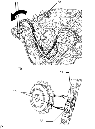
*1 Mark Plate (Orange) *2 Timing Mark Align the mark plates and timing marks as shown in the illustration and install the chain sub-assembly.
Tech Tips
The camshaft mark plates are orange.
-
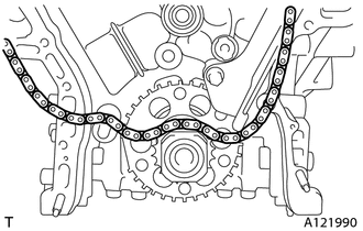
Rest the chain sub-assembly on top of the crankshaft.
-
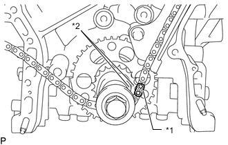
*1 Inner Chain Plate *2 Outer Chain Plate *a Chain sub-assembly between banks *b When idle sprocket assembly is reused *c Mark Turn Turn the camshaft timing gear assembly on bank 1 counterclockwise to tighten the chain sub-assembly between the banks.
Note
When the idle sprocket assembly is reused, align the chain plate with the mark where the plate had been in order to tighten the chain sub-assembly between the banks.
-
*1 Mark Plate (Yellow) *2 Timing Mark Align the mark plate and timing mark as shown in the illustration and install the chain sub-assembly onto the crankshaft timeng gear or sprocket.
Tech Tips
The crankshaft mark plate is yellow.
-
Temporarily tighten the crankshaft pulley set bolt.
-
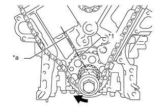
*1 Timing Mark *a Bank 1 Cylinder block Bore Center Line (TDC/compression) Turn Turn the crankshaft clockwise to set the timing mark to the bank 1 cylinder block bore center line (TDC/compression).
-
-
INSTALL CHAIN TENSIONER SLIPPER
-
Install the chain tensioner slipper.
-
-
INSTALL NO. 1 CHAIN TENSIONER ASSEMBLY
-
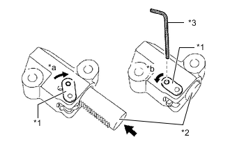
*1 Stopper Plate *2 Plunger *3 Hexagon Wrench *a Move Stopper Plate upward *b Move Stopper Plate downward Move the stopper plate upward to release the lock, and push the plunger deep into the No. 1 chain tensioner assembly.
-
Move the stopper plate downward to set the lock, and insert a hexagon wrench into the hole of the stopper plate.
-
Install the No. 1 chain tensioner assembly with the 2 bolts.
- Torque:
- 10 N*m { 102 kgf*cm, 7 ft.*lbf }
-
Remove the hexagon wrench from the No. 1 chain tensioner assembly.
-
-
INSPECT VALVE TIMING
-
Check the camshaft timing marks.
Note
-
Check each timing mark from a viewpoint directly inline with the center of the camshaft and the timing mark on each camshaft timing gear.
-
If the timing marks are checked from any other viewpoint, the valve timing may appear misaligned.
-
-
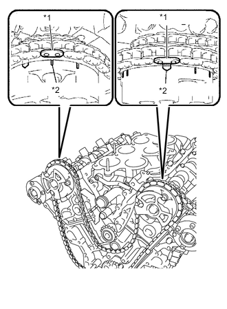
Check that each camshaft timing mark is positioned as shown in the illustration.
*1 Timing Mark - - *a Viewpoint - - Tech Tips
For the intake camshaft:
Be sure to check mark A at the point when marks B, C, and D are positioned in line.
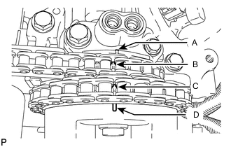
If the marks are checked from any other viewpoint, they cannot be checked correctly.
-
If the valve timing is misaligned, reinstall the chain sub-assembly.
-
Remove the crankshaft pulley set bolt.
-
-
INSTALL ENGINE WATER PUMP ASSEMBLY
-
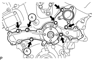
Install a new water pump gasket and the engine water pump assembly with the 7 bolts.
- Torque:
- 11 N*m { 112 kgf*cm, 8 ft.*lbf }
Note
-
Be sure to replace the 2 bolts (A) with new ones or reuse them after applying adhesive.
-
Tighten the bolts within 3 minute after applying adhesive.
Adhesive Toyota Genuine Adhesive 1344, Three Bond 1344 or equivalent
-
-
INSTALL TIMING CHAIN OR BELT COVER SUB-ASSEMBLY
-
INSTALL TIMING GEAR CASE OR TIMING CHAIN CASE OIL SEAL
-
INSTALL TIMING CHAIN COVER PLATE
-
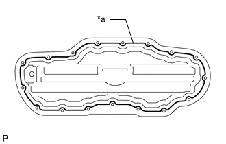
INSTALL NO. 1 OIL PAN BAFFLE PLATE
-
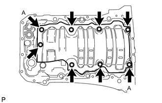
Temporarily install the No. 1 oil pan baffle plate with the 8 bolts.
-
Tighten the 2 bolts A shown in the illustration.
- Torque:
- 10 N*m { 102 kgf*cm, 7 ft.*lbf }
-
Tighten the other 6 bolt.
- Torque:
- 10 N*m { 102 kgf*cm, 7 ft.*lbf }
-
-
INSTALL OIL STRAINER SUB-ASSEMBLY
-
Install a new oil strainer gasket and the oil strainer sub-assembly with the 3 nuts.
- Torque:
- 10 N*m { 102 kgf*cm, 7 ft.*lbf }
-
-
INSTALL OIL PAN SUB-ASSEMBLY
-
Install 2 new O-rings.
-
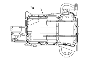
*a Seal Packing Apply seal packing in a continuous line as shown in the illustration.
Seal packing Toyota Genuine Seal Packing Black, Three Bond 1207B or equivalent Seal diameter 3.0 to 4.0 mm (0.118 to 0.156 in.) Note
-
Check the bolts and bolt holes and clean them.
-
Remove any oil from the contact surface.
-
Install the oil pan sub-assembly within 3 minutes and tighten the bolts and nuts within 15 minutes after applying seal packing.
-
Do not add engine oil for at least 2 hours after installation.
-
Do not start the engine for at least 2 hours after installation.
-
-
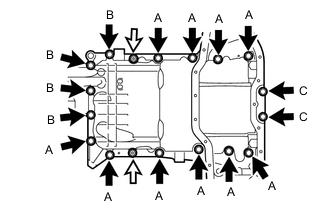
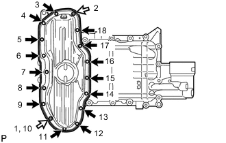
Bolt 
Nut Install the oil pan sub-assembly and temporarily tighten the 16 bolts and 2 nuts in several steps.
Standard Bolt: Item Length Bolt A 25 mm (0.984 in.) Bolt B 45 mm (1.77 in.) Bolt C 16 mm (0.630 in.) -
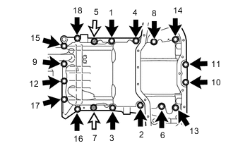
Bolt Nut Tighten the 16 bolts and 2 nuts in the order shown in the illustration.
- Torque:
- for bolt A, B and nut
- 21 N*m { 214 kgf*cm, 15 ft.*lbf }
- for bolt C
- 10 N*m { 102 kgf*cm, 7 ft.*lbf }
-
-
INSTALL NO. 2 OIL PAN SUB-ASSEMBLY
-
*a Seal Packing Apply seal packing in a continuous line as shown in the illustration.
Seal packing Toyota Genuine Seal Packing Black, Three Bond 1207B or equivalent Seal diameter 4.0 to 6.0 mm (0.156 to 0.236 in.) Note
-
Check the bolts and bolt holes and clean them.
-
Remove any oil from the contact surface.
-
Install the No. 2 oil pan sub-assembly within 3 minutes and tighten the bolts and nuts within 15 minutes after applying seal packing.
-
Do not add engine oil for at least 2 hours after installation.
-
Do not start the engine for at least 2 hours after installation.
-
-
Bolt Nut Install the No. 2 oil pan sub-assembly and tighten the 15 bolts and 2 nuts in several steps in the order shown in the illustration.
- Torque:
- 10 N*m { 102 kgf*cm, 7 ft.*lbf }
-
-
INSTALL OIL PAN DRAIN PLUG
-
Install a new gasket and the oil pan drain plug.
- Torque:
- 40 N*m { 408 kgf*cm, 30 ft.*lbf }
-
-
INSTALL SPARK PLUG TUBE GASKET
-
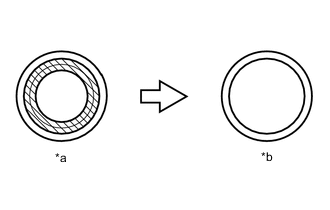
*a Before cutting off *b After cutting off 
Area to be cut off Using a cutter, cut off the sealing part of the removed spark plug tube gasket.
-
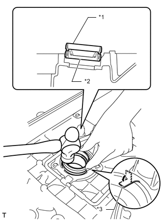
*1 Spark Plug Tube Gasket without Sealing Part *2 New Spark Plug Tube Gasket *3 Claw Using a spark plug tube gasket which has had the sealing part cut off, uniformly press in a new spark plug tube gasket all the way.
Note
-
Keep the lip free of foreign matter.
-
Do not tap in the spark plug tube gasket at an angle.
Tech Tips
If a spark plug tube gasket that will be used to install a new spark plug tube gasket is deformed, and cannot be positioned on a new spark plug tube gasket, correct the deformation using pliers.
-
-
Return the claws of the ventilation baffle plate to their original positions.
-
-
POUR ENGINE OIL
Tech Tips
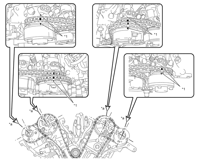
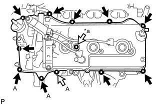
Before installing the cylinder head cover sub-assemblies, pour engine oil into the locations shown in the illustration.
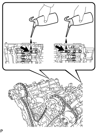
-
INSTALL CYLINDER HEAD COVER SUB-ASSEMBLY
-
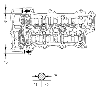
*1 timing chain cover sub-assembly *2 camshaft housing sub-assembly RH *a 2.0 to 3.0 mm (0.0787 to 0.118 in.) *b 5.0 to 10.0 mm (0.197 to 0.394 in.) Seal Packing Apply seal packing as shown in the illustration.
Seal packing Toyota Genuine Seal Packing Black, Three Bond 1207B or equivalent Note
-
Remove any oil from the contact surface.
-
Install the cylinder head cover sub-assembly within 3 minutes and tighten the bolts within 15 minutes after applying seal packing.
-
Do not add engine oil for at least 2 hours after installation.
-
Do not start the engine for at least 2 hours after installation.
-
-
Install 3 new gaskets to the No. 1, No. 2 and No. 7 camshaft bearing caps.
-
Install a new cylinder head cover gasket to the cylinder head cover sub-assembly.
-
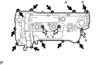
*a Bolt with cylinder head cover seal washer Apply adhesive 1324 to these bolts Apply adhesive 1324 to the threads of the 11 bolts indicated by the black arrows in the illustration.
Adhesive Toyota Genuine Adhesive 1324, Three Bond 1324 or equivalent Note
Tighten the bolts within 3 minute after applying adhesive.
-
Install the cylinder head cover sub-assembly and 2 new seal washers with the 14 bolts.
- Torque:
- for bolt A
- 21 N*m { 214 kgf*cm, 15 ft.*lbf }
- except bolt A
- 10 N*m { 102 kgf*cm, 7 ft.*lbf }
-
-
INSTALL CYLINDER HEAD COVER SUB-ASSEMBLY LH
-
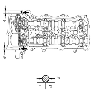
*1 timing chain cover sub-assembly *2 camshaft housing sub-assembly LH *a 2.0 to 3.0 mm (0.0787 to 0.118 in.) *b 5.0 to 10.0 mm (0.197 to 0.394 in.) Seal Packing Apply seal packing as shown in the illustration.
Seal packing Toyota Genuine Seal Packing Black, Three Bond 1207B or equivalent Note
-
Remove any oil from the contact surface.
-
Install the cylinder head cover sub-assembly LH within 3 minutes and tighten the bolts within 15 minutes after applying seal packing.
-
Do not add engine oil for at least 2 hours after installation.
-
Do not start the engine for at least 2 hours after installation.
-
-
Install 3 new gaskets to the No. 3, No. 4 and No. 7 camshaft bearing caps.
-
Install a new cylinder head cover gasket LH to the cylinder head cover sub-assembly LH.
-
*a Bolt with cylinder head cover seal washer Apply adhesive 1324 to these bolts Apply adhesive 1324 to the threads of the 10 bolts indicated by the black arrows in the illustration.
Adhesive Toyota Genuine Adhesive 1324, Three Bond 1324 or equivalent Note
Tighten the bolts within 3 minute after applying adhesive.
-
Install the cylinder head cover sub-assembly LH and a new seal washer with the 12 bolts.
- Torque:
- for bolt A
- 21 N*m { 214 kgf*cm, 15 ft.*lbf }
- except bolt A
- 10 N*m { 102 kgf*cm, 7 ft.*lbf }
-
-
INSTALL REAR WATER BY-PASS JOINT
-
Install 2 new water outlet gaskets and a new water outlet pipe O-ring.
Tech Tips
Apply water to the water outlet pipe O-ring.
-
Install the rear water by-pass joint with the 2 bolts and 4 nuts.
- Torque:
- 10 N*m { 102 kgf*cm, 7 ft.*lbf }
Note
Be careful that the water outlet pipe O-ring does not get caught between the parts.
-
-
INSTALL WATER INLET SUB-ASSEMBLY WITH THERMOSTAT
-
Install a new No. 1 water inlet housing gasket and water inlet sub-assembly with thermostat with the 3 nuts.
- Torque:
- 10 N*m { 102 kgf*cm, 7 ft.*lbf }
-
-
INSTALL WATER INLET
-
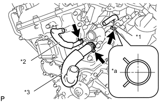
*1 No. 4 Water By-pass Hose *2 No. 6 Water By-pass Hose *3 No. 3 Water By-pass Hose *a RH Side Connect the No. 3, No. 4 and No. 6 water by-pass hoses on engine side.
Tech Tips
-
Install the water by-pass hoses so that the paint marks are positioned on the cylinder head side.
-
Attach the No. 4 water by-pass hose clamp as shown in the illustration.
-
-
Install a new No. 1 water inlet housing gasket and water outlet pipe O-ring.
-
Install the water inlet with the 4 bolts and nut.
- Torque:
- 10 N*m { 102 kgf*cm, 7 ft.*lbf }
Note
Be careful not to allow the No. 1 water inlet housing gasket and water outlet pipe O-ring to get caught between the parts.
-
Connect the No. 3, No. 4 and No. 6 water by-pass hoses to the water inlet.
-
-
INSTALL CRANKSHAFT PULLEY
-
INSTALL OIL FILTER CAP ASSEMBLY
-
INSTALL ENGINE OIL PRESSURE SWITCH ASSEMBLY
-
INSTALL CYLINDER BLOCK WATER DRAIN COCK SUB-ASSEMBLY
-
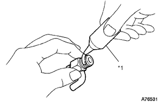
*1 Adhesive Apply adhesive to 2 or 3 threads at the end of the cylinder block water drain cock sub-assembly.
Adhesive Toyota Genuine Adhesive 1324, Three Bond 1324 or equivalent Note
Install the cylinder block water drain cock sub-assembly within 3 minutes after applying adhesive.
-
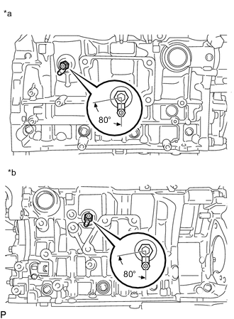
*a for Bank 1 *b for Bank 2 Install the cylinder block water drain cock sub-assemblies as shown in the illustration.
- Torque:
- 30 N*m { 306 kgf*cm, 22 ft.*lbf }
Note
-
Do not rotate the cylinder block water drain cock sub-assembly by more than 1 revolution (360°) after tightening the cylinder block water drain cock sub-assembly to the specified torque.
-
Do not loosen the cylinder block water drain cock sub-assembly after setting it correctly.
-
Install the 2 water drain cock plugs to the 2 cylinder block water drain cock sub-assemblies.
- Torque:
- 12.7 N*m { 130 kgf*cm, 9 ft.*lbf }
-
-
INSTALL NO. 1 OIL PIPE
-
Make sure that there is no foreign matter on the mesh of the oil control valve filter LH.
Note
Do not touch the mesh when installing the oil control valve filter LH.
-
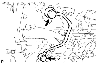
*1 Oil Pipe Union *2 Oil Check Valve Bolt Install the oil control valve filter LH to the oil pipe union. Install 2 new gaskets and temporarily install the No. 1 oil pipe on the cylinder head cover sub-assembly LH side.
-
Install a new gasket and temporarily install the No. 1 oil pipe on the cylinder head LH side with the oil check valve bolt.
-
Tighten the oil pipe union on the cylinder head cover sub-assembly LH side.
- Torque:
- 60 N*m { 612 kgf*cm, 44 ft.*lbf }
-
Tighten the oil check valve bolt on the cylinder head LH side.
- Torque:
- 60 N*m { 612 kgf*cm, 44 ft.*lbf }
Note
If the link that connects the gaskets is broken, remove the connecting link by using nippers or similar tools.
-
-
INSTALL NO. 2 OIL PIPE
-
Make sure that there is no foreign matter on the mesh of the oil control valve filter RH.
Note
Do not touch the mesh when installing the oil control valve filter RH.
-
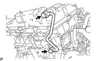
*1 Oil Pipe Union *2 Oil Check Valve Bolt Install the oil control valve filter RH to the oil pipe union. Install 2 new gaskets and temporarily install the No. 2 oil pipe on the cylinder head cover sub-assembly side.
-
Install a new gasket and temporarily install the No. 2 oil pipe on the cylinder head sub-assembly side with the oil check valve bolt.
-
Tighten the oil pipe union on the cylinder head cover sub-assembly side.
- Torque:
- 60 N*m { 612 kgf*cm, 44 ft.*lbf }
-
Tighten the oil check valve bolt on the cylinder head sub-assembly side.
- Torque:
- 60 N*m { 612 kgf*cm, 44 ft.*lbf }
Note
If the link that connects the gaskets is broken, remove the connecting link by using nippers or similar tools.
-
-
INSTALL CRANKSHAFT POSITION SENSOR
-
INSTALL ENGINE COOLANT TEMPERATURE SENSOR
-
INSTALL ENGINE OIL LEVEL SENSOR
-
INSTALL CAMSHAFT TIMING OIL CONTROL VALVE ASSEMBLY (for Exhaust Side of Bank 2)
-
INSTALL CAMSHAFT TIMING OIL CONTROL VALVE ASSEMBLY (for Intake Side of Bank 2)
-
INSTALL CAMSHAFT TIMING OIL CONTROL VALVE ASSEMBLY (for Intake Side of Bank 1)
-
INSTALL CAMSHAFT TIMING OIL CONTROL VALVE ASSEMBLY (for Exhaust Side of Bank 1)
-
INSTALL VVT SENSOR (for Exhaust Side of Bank 2)
-
INSTALL VVT SENSOR (for Intake Side of Bank 2)
-
INSTALL VVT SENSOR (for Exhaust Side of Bank 1)
-
INSTALL VVT SENSOR (for Intake Side of Bank 1)
-
INSTALL PCV VALVE (VENTILATION VALVE SUB-ASSEMBLY)
-
INSTALL SPARK PLUG
-
INSTALL RADIATOR CAP SUB-ASSEMBLY
-
Install the radiator cap sub-assembly.
-
-
INSTALL OIL FILLER CAP SUB-ASSEMBLY
-
Install a new gasket.
-
Install the oil filler cap sub-assembly.
-
-
INSTALL FUEL INJECTOR SEAL
-
INSTALL FUEL INJECTOR ASSEMBLY
-
INSTALL FUEL DELIVERY PIPE SUB-ASSEMBLY
-
INSTALL NO. 2 FUEL DELIVERY PIPE SUB-ASSEMBLY