CYLINDER HEAD REASSEMBLY

CAUTION / NOTICE / HINT
Tech Tips
Perform "Inspection After Repairs" after replacing the cylinder head sub-assembly.
Click here (w/o Canister Pump Module)
Click here (w/ Canister Pump Module)
PROCEDURE
-
INSTALL STUD BOLT
Note
If a stud bolt is deformed or its threads are damaged, replace it.
-
Using an E8 and E10 "TORX" socket wrench, install the stud bolts.
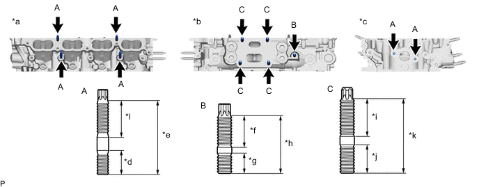
*a Intake side *b Exhaust Side *c Front Side *d 16.7 mm (0.658 in.) *e 51.7 mm (2.04 in.) *f 23 mm (0.906 in.) *g 15 mm (0.591 in.) *h 40 mm (1.58 in.) *i 26.5 mm (1.04 in.) *j 20 mm (0.787 in.) *k 50 mm (1.97 in.) *l 26 mm (1.02 in.) - Torque:
- for stud bolt A
- 9.0 N*m { 92 kgf*cm, 80 in.*lbf }
- for stud bolt B, C
- 22 N*m { 224 kgf*cm, 16 ft.*lbf }
-
-
INSTALL NO. 1 STRAIGHT SCREW PLUG
Note
If coolant leaks from a No. 1 straight screw plug or the plug is corroded, replace it.
-
Using a 14 mm straight hexagon wrench, install 6 new gaskets and the 6 No. 1 straight screw plugs.
- Torque:
- 135 N*m { 1377 kgf*cm, 100 ft.*lbf }
-
-
INSTALL VALVE SPRING SEAT
-
Install the valve spring seats to the cylinder head sub-assembly.
-
-
INSTALL VALVE STEM OIL SEAL
-
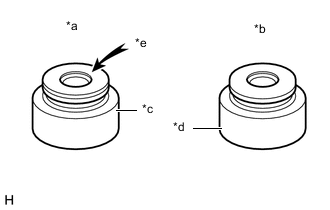
*a Intake Side *b Exhaust Side *c Brown *d Gray *e "NOK" Mark Apply a light coat of engine oil to new valve stem oil seals.
Note
Pay attention when installing the intake valve stem oil seals and exhaust valve stem oil seals. For example, installing the intake valve stem oil seal onto the exhaust side or installing the exhaust valve stem oil seal onto the intake side can cause installation problems later.
Tech Tips
The intake valve stem oil seals are brown and the exhaust valve stem oil seals are gray.
-
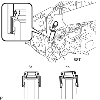
*a CORRECT *b INCORRECT Using SST, push in the valve stem oil seals.
- SST
- 09201-41020
Note
Failure to use SST will cause the valve stem oil seal to be damaged or improperly seated.
-
-
INSTALL INTAKE VALVE
-
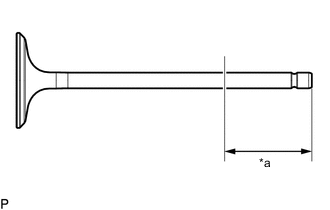
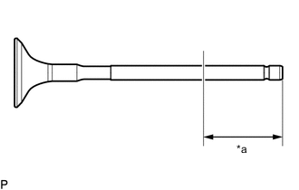
*a 30 mm (1.18 in.) or more Apply plenty of engine oil to the tip area of the intake valve shown in the illustration.
-
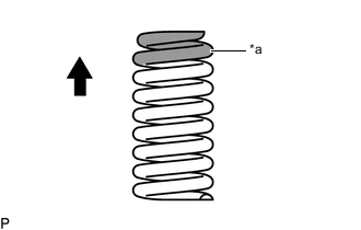
*a Paint Mark (White) 
Upper Side Install the intake valve, compression spring and valve spring retainer to the cylinder head sub-assembly.
Note
-
Install the same parts in the same combination to their original locations.
-
The compression spring has a different identification color for the intake side and exhaust side.
Confirm the color during installation.
-
-
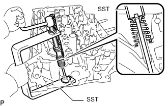
Using SST and wooden blocks, compress the compression spring and install the valve spring retainer locks.
- SST
- 09202-70020
- 09202-00021
-
Using a plastic-faced hammer, lightly tap the valve stem tip to ensure a proper fit.
Note
Be careful not to damage the valve spring retainer.
-
-
INSTALL EXHAUST VALVE
-
*a 30 mm (1.18 in.) or more Apply plenty of engine oil to the tip area of the exhaust valve shown in the illustration.
-
*a Paint Mark (Purple) Upper Side Install the exhaust valve, compression spring and valve spring retainer to the cylinder head sub-assembly.
Note
-
Install the same parts in the same combination to their original locations.
-
The compression spring has a different identification color for the intake side and exhaust side.
Confirm the color during installation.
-
-
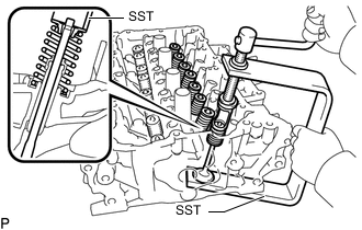
Using SST and wooden blocks, compress the compression spring and install the valve spring retainer locks.
- SST
- 09202-70020
- 09202-00021
-
Using a plastic-faced hammer, lightly tap the valve stem tip to ensure a proper fit.
Note
Be careful not to damage the valve spring retainer.
-