OIL PUMP REMOVAL

PROCEDURE
-
REMOVE ENGINE ASSEMBLY
-
REMOVE ENGINE WIRE
-
REMOVE THROTTLE BODY WITH MOTOR ASSEMBLY
-
REMOVE INTAKE AIR SURGE TANK ASSEMBLY
-
REMOVE NO. 2 FUEL TUBE SUB-ASSEMBLY
-
REMOVE NO. 1 ENGINE COVER SUB-ASSEMBLY
-
for Bank 1:
Remove the 2 clips and No. 1 engine cover from the cylinder head cover sub-assembly.
-
for Bank 2:
Remove the bolt and No. 1 engine cover from the No. 1 fuel tube sub-assembly.
-
-
REMOVE NO. 1 FUEL TUBE SUB-ASSEMBLY
-
REMOVE NO. 1 FUEL PIPE SUB-ASSEMBLY
-
REMOVE FUEL PUMP ASSEMBLY (for High Pressure)
-
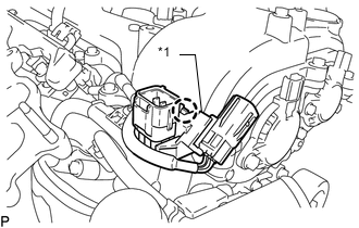
DISCONNECT WIRE HARNESS
-
for Bank 1:
-
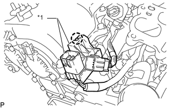
*1 No. 6 Engine Wire Disengage the claw and disconnect the No. 6 engine wire from the cylinder head cover sub-assembly.
-
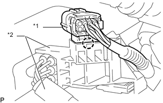
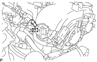
*1 No. 5 Engine Wire *2 No. 6 Engine Wire Disengage the claw and disconnect the No. 5 engine wire from the No. 6 engine wire.
-
-
for Bank 2:
-
*1 No. 7 Engine Wire Disengage the claw and disconnect the No. 7 engine wire from the cylinder head cover sub-assembly LH.
-
Disengage the clamp.
-

*1 No. 8 Engine Wire *2 No. 7 Engine Wire Disengage the claw and disconnect the No. 8 engine wire from the No. 7 engine wire.
-
-
-
REMOVE FUEL DELIVERY PIPE WITH SENSOR ASSEMBLY
-
REMOVE INTAKE MANIFOLD
-
REMOVE V-RIBBED BELT TENSIONER ASSEMBLY
-
REMOVE NO. 2 IDLER PULLEY SUB-ASSEMBLY
-
REMOVE WATER PUMP PULLEY
-
REMOVE NO. 1 WATER BY-PASS PIPE (w/ Oil Cooler)
-
REMOVE NO. 6 WATER BY-PASS HOSE
-
REMOVE NO. 2 WATER BY-PASS HOSE
-
REMOVE NO. 3 WATER BY-PASS HOSE
-
REMOVE NO. 2 WATER BY-PASS HOSE ASSEMBLY
-
REMOVE WATER INLET SUB-ASSEMBLY WITH THERMOSTAT
-
REMOVE WATER OUTLET SUB-ASSEMBLY
-
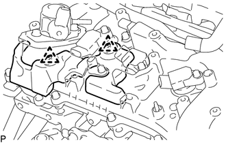
REMOVE CAMSHAFT TIMING OIL CONTROL SOLENOID ASSEMBLY (for Intake Side of Bank 1)
-
REMOVE CAMSHAFT TIMING OIL CONTROL SOLENOID ASSEMBLY (for Exhaust Side of Bank 1)
-
REMOVE CAMSHAFT TIMING OIL CONTROL SOLENOID ASSEMBLY (for Intake Side of Bank 2)
-
REMOVE CAMSHAFT TIMING OIL CONTROL SOLENOID ASSEMBLY (for Exhaust Side of Bank 2)
-
REMOVE WIRE HARNESS CLAMP BRACKET
-
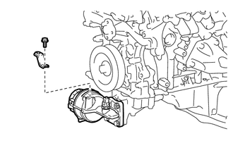
Remove the wire harness clamp bracket with the bolt from oil filter bracket sub-assembly.
-
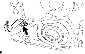
Remove the wire harness clamp bracket with the bolt from timing chain cover assembly.
-
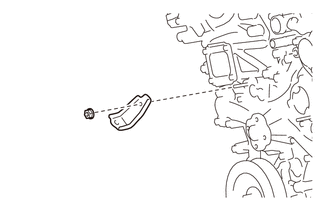
Remove the wire harness clamp bracket with the nut from timing chain cover assembly.
-
-
REMOVE OIL FILTER BRACKET SUB-ASSEMBLY
-
Remove the oil filter bracket sub-assembly and gasket with the 2 bolts and 2 nuts.
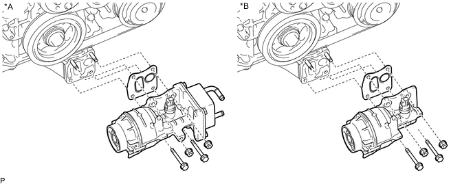
*A w/ Oil Cooler *B w/o Oil Cooler
-
-
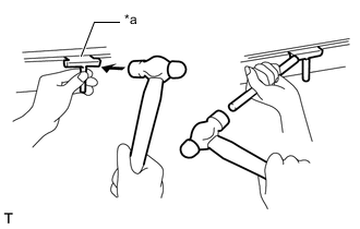
REMOVE CRANKSHAFT PULLEY
-
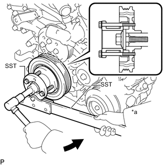
*a Hold 
Turn Using SST, hold the crankshaft pulley and loosen the pulley bolt. Continue to loosen the bolt until only 2 or 3 threads are screwed into the crankshaft.
- SST
- 09213-54015 ( 91651-60855 )
- 09330-00021
-
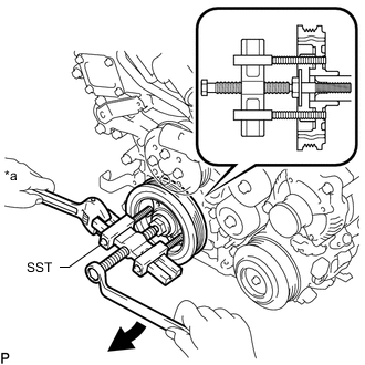
*a Hold Turn Using the pulley set bolt and SST, remove the crankshaft pulley and pulley bolt.
- SST
- 09950-50013 ( 09951-05010, 09952-05010, 09953-05020, 09954-05031 )
-
-
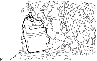
REMOVE IGNITION COIL ASSEMBLY
-
REMOVE CYLINDER HEAD COVER SUB-ASSEMBLY LH
-
*1 VVT Sensor Remove the 2 bolts and 2 VVT sensors from the cylinder head cover sub-assembly LH.
-
Remove the 14 bolts and cylinder head cover sub-assembly LH from the camshaft housing sub-assembly LH.
-
Remove the camshaft bearing cap oil hole gasket LH.
-
Remove the 2 gaskets and cylinder head cover gasket.
-
-
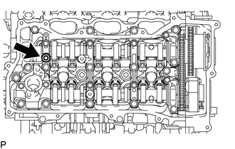
REMOVE CYLINDER HEAD COVER SUB-ASSEMBLY
-
*1 VVT Sensor Remove the 2 bolts and 2 VVT sensors from the cylinder head cover sub-assembly.
-
Remove the 13 bolts and cylinder head cover sub-assembly from the camshaft housing sub-assembly RH.
-
Remove the camshaft bearing cap oil hole gasket RH.
-
Remove the 2 gaskets and cylinder head cover gasket.
-
-
REMOVE SPARK PLUG TUBE GASKET
-
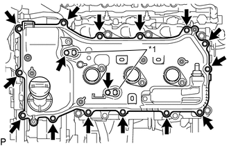
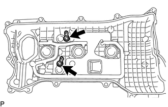
REMOVE NO. 2 OIL PAN SUB-ASSEMBLY
-
Bolt 
Nut Remove the 15 bolts and 2 nuts.
-
*a Oil Pan Seal Cutter Insert the blade of an oil pan seal cutter between the oil pans. Cut through the applied sealer and remove the No. 2 oil pan sub-assembly.
Note
Be careful not to damage the contact surfaces of the oil pans.
-
-
REMOVE ENGINE OIL LEVEL SENSOR
-
REMOVE OIL LEVEL SENSOR BRACKET
-
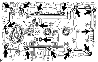
REMOVE OIL PAN SUB-ASSEMBLY
-
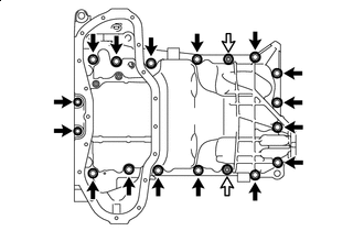
Bolt Nut Remove the 16 bolts and 2 nuts.
Tech Tips
Be sure to clean the bolts and stud bolts and check the threads for cracks or other damage.
-
*a LH Side *b RH Side Remove the oil pan sub-assembly by prying between the oil pan sub-assembly and cylinder block sub-assembly with a screwdriver.
Note
Be careful not to damage the contact surfaces of the cylinder block sub-assembly and oil pan sub-assembly.
Tech Tips
Tape the screwdriver tip before use.
-
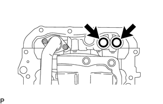
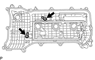
Remove the 2 O-rings from the timing chain cover sub-assembly.
-
-
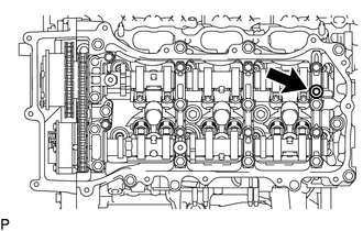
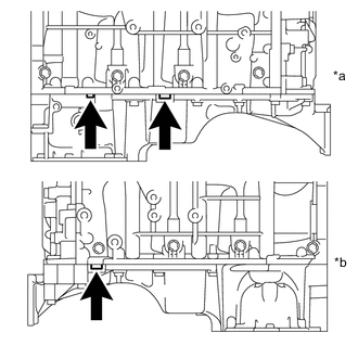
REMOVE OIL STRAINER SUB-ASSEMBLY
-
Remove the 3 nuts, oil strainer sub-assembly and gasket.
-
-
REMOVE TIMING CHAIN COVER PLATE
-
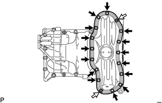
REMOVE TIMING CHAIN COVER SUB-ASSEMBLY
-
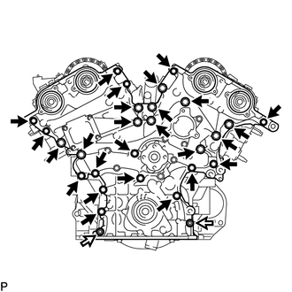
Bolt Nut Remove the 26 bolts and 2 nuts shown in the illustration.
-
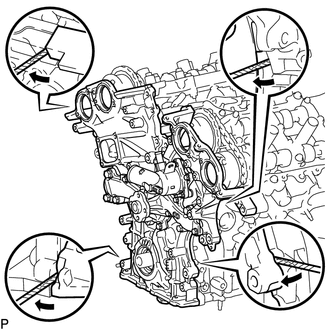
Remove the timing chain cover sub-assembly by prying between the timing chain cover sub-assembly and cylinder head sub-assembly or cylinder block sub-assembly with a screwdriver.
Note
Be careful not to damage the contact surfaces of the cylinder head sub-assembly, cylinder block sub-assembly and timing chain cover sub-assembly.
Tech Tips
Tape the screwdriver tip before use.
-
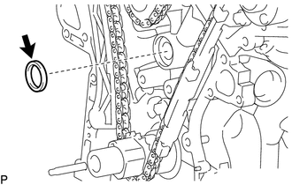
Remove the oil pump gasket from the cylinder block sub-assembly.
-
-
REMOVE TIMING CHAIN CASE OIL SEAL
-
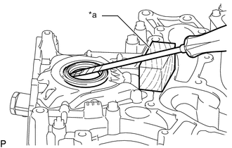
*a Wooden Block Using a screwdriver and wooden block, pry out the timing chain case oil seal.
Note
Do not damage the surface of the oil seal press fit hole.
Tech Tips
Tape the screwdriver tip before use.
-