OIL PUMP INSTALLATION
PROCEDURE
-
INSTALL TIMING CHAIN OR BELT COVER SUB-ASSEMBLY
-
Remove any old packing material remaining on the sealing surfaces before applying seal packing.
-
Clean and degrease the contact surfaces of the timing chain or belt cover sub-assembly, cylinder head sub-assembly, cylinder head LH and cylinder block sub-assembly, and confirm that no oil, moisture or other foreign matter remains on the surfaces.
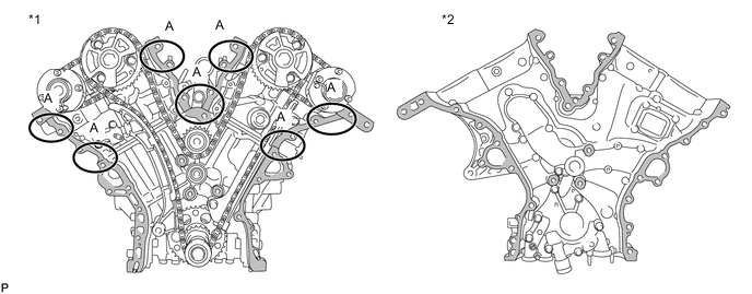
*1 Cylinder Head Sub-assembly, Cylinder Head LH and Cylinder Block Sub-assembly *2 Timing Chain Or Belt Cover Sub-assembly 
Area to be cleaned and degreased - - Note
Be sure to clean and degrease the contact surfaces, especially the surfaces indicated by A in the illustration.
-
Install a new gasket.
-
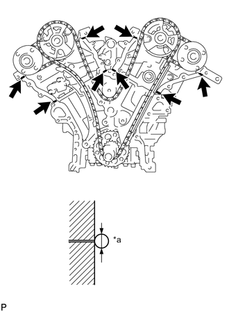
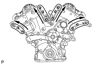
*a 3.0 mm (0.118 in.) or more Apply seal packing in a continuous line to the engine unit as shown in the illustration.
Seal Packing Toyota Genuine Seal Packing Black, Three Bond 1207B or equivalent Seal Diameter 3.0 mm (0.118 in.) or more Note
-
If the contact surfaces are wet, wipe them with an oil-free cloth before applying seal packing.
-
Check the bolts and bolt holes, and clean and degrease them.
-
Install the timing chain cover sub-assembly within 3 minutes and tighten the bolts within 10 minutes after applying seal packing.
-
Do not add engine oil for at least 2 hours after installing the timing chain or belt cover sub-assembly.
-
Do not start the engine for at least 2 hours after installing the timing chain or belt cover sub-assembly.
-
-
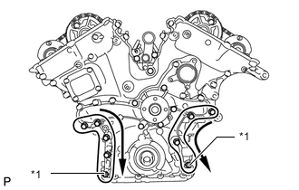
Apply seal packing in a line to the timing chain or belt cover sub-assembly as shown in the following illustration.
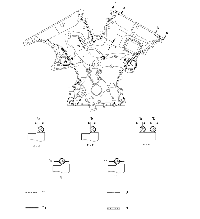
*a 3.0 to 4.0 mm (0.118 to 0.157 in.) *b 2.0 to 3.0 mm (0.0787 to 0.118 in.) *c 6.0 mm (0.236 in.) or more *d 4.5 mm (0.177 in.) or more *e 20 mm (0.787 in.) *f Dashed line area
(Seal packing: Toyota Genuine Seal Packing Black, Three Bond 1207B or equivalent)
*g Alternate long and short dashed line area
(Seal packing: Toyota Genuine Seal Packing 1282B, Three Bond 1282B or equivalent)
*h Continuous line area
(Seal packing: Toyota Genuine Seal Packing Black, Three Bond 1207B or equivalent)
*i Diagonal line area
(Seal packing: Toyota Genuine Seal Packing Black, Three Bond 1207B or equivalent)
- - Seal Packing Application Chart Area Seal Packing Diameter Application Position from Inside Seal Line Diagonal Line Area 6.0 mm (0.236 in.) or more 3.0 to 4.0 mm (0.118 to 0.157 in.) Continuous Line Area 4.5 mm (0.177 in.) or more 3.0 to 4.0 mm (0.118 to 0.157 in.) Dashed Line Area 3.5 mm (0.138 in.) or more
-
a - a: 3.0 to 4.0 mm (0.118 to 0.157 in.)
-
b - b: 2.0 to 3.0 mm (0.0787 to 0.118 in.)
Alternate Long and short Dashed Line Area 3.5 mm (0.138 in.) or more 2.0 to 3.0 mm (0.0787 to 0.118 in.) Seal Packing Toyota Genuine Seal Packing Black, Three Bond 1207B or equivalent Toyota Genuine Seal Packing 1282B, Three Bond 1282B or equivalent Note
-
If the contact surfaces are wet, wipe them with an oil-free cloth before applying seal packing.
-
Check the bolts and bolt holes, and clean and degrease them.
-
Install the timing chain or belt cover sub-assembly within 3 minutes and tighten the bolts within 10 minutes after applying seal packing.
-
Do not add the engine oil for at least 2 hours after installing the timing chain or belt cover sub-assembly.
-
Do not start the engine for at least 2 hours after installing the timing chain or belt cover sub-assembly.
-
-
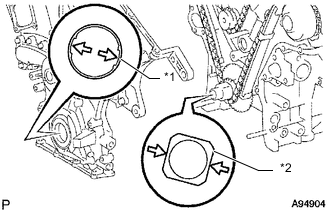
*1 Drive Rotor Spline *2 Crankshaft Align the oil pump's drive rotor spline and crankshaft as shown in the illustration. Install the timing chain or belt cover sub-assembly.
-
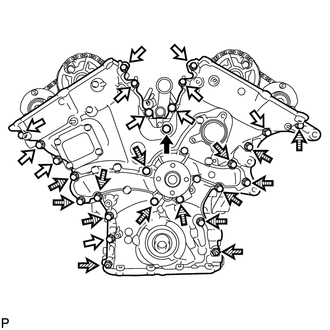

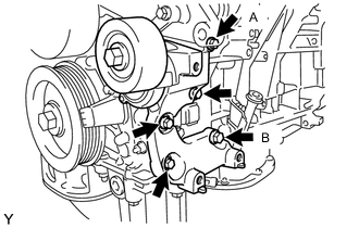
Bolt A 
Bolt B 
Nut 
Bolt C Temporarily tighten the timing chain or belt cover sub-assembly with the 25 bolts and 2 nuts.
Bolt Length: Item Specified Condition Bolt A 50 mm (1.97 in.) Bolt B 25 mm (0.984 in.) or 28 mm (1.102 in.) Bolt C 55 mm (2.17 in.) Note
-
Make sure that there is no oil on the bolt threads.
-
Check the bolts and bolt holes, and clean and degrease them.
-
-
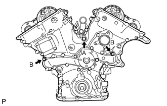
Fully tighten the 3 bolts shown in the illustration.
- Torque:
- for bolt A
- 43 N*m { 438 kgf*cm, 32 ft.*lbf }
- for bolt B
- 21 N*m { 214 kgf*cm, 15 ft.*lbf }
-
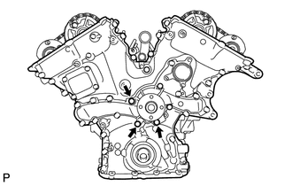
Fully tighten the 3 bolts shown in the illustration.
- Torque:
- 21 N*m { 214 kgf*cm, 15 ft.*lbf }
-
*1 Nut Fully tighten the 7 bolts and 2 nuts shown in the illustration.
- Torque:
- 21 N*m { 214 kgf*cm, 15 ft.*lbf }
Tech Tips
Tighten the bolts and nuts in order from upper to lower as shown in the illustration.
-
Fully tighten the 12 bolts shown in the illustration.
- Torque:
- 21 N*m { 214 kgf*cm, 15 ft.*lbf }
Tech Tips
Tighten the bolts in order from lower to upper as shown in the illustration.
-
Install the wiring harness clamp bracket with the bolt.
- Torque:
- 10 N*m { 102 kgf*cm, 7 ft.*lbf }
-
-
INSTALL TIMING GEAR CASE OR TIMING CHAIN CASE OIL SEAL
-
INSTALL SPARK PLUG TUBE GASKET
-
INSTALL CYLINDER HEAD COVER SUB-ASSEMBLY
-
INSTALL CYLINDER HEAD COVER SUB-ASSEMBLY LH
-
INSTALL NO. 2 OIL PIPE
-
INSTALL NO. 1 OIL PIPE
-
INSTALL OIL STRAINER SUB-ASSEMBLY
-
INSTALL OIL PAN SUB-ASSEMBLY
-
INSTALL NO. 2 OIL PAN SUB-ASSEMBLY
-
INSTALL CRANKSHAFT PULLEY
-
INSTALL IGNITION COIL ASSEMBLY
-
INSTALL WATER INLET
-
INSTALL NO. 2 ENGINE COVER
-
INSTALL INJECTOR DRIVER
-
INSTALL NO. 1 ENGINE COVER
-
INSTALL WATER PUMP PULLEY
-
INSTALL NO. 2 IDLER PULLEY SUB-ASSEMBLY
-
INSTALL V-RIBBED BELT TENSIONER ASSEMBLY
-
Temporarily install the V-ribbed belt tensioner assembly with the bolt A and bolt B.
-
Tighten the 5 bolts to install the V-ribbed belt tensioner assembly.
- Torque:
- 43 N*m { 438 kgf*cm, 32 ft.*lbf }
-
-
INSTALL COMPRESSOR AND MAGNETIC CLUTCH
-
INSTALL GENERATOR ASSEMBLY
-
INSTALL V-RIBBED BELT
-
INSTALL FUEL PUMP ASSEMBLY (for High Pressure)
-
INSTALL ENGINE WIRE
-
INSTALL NO. 1 ENGINE HANGER
-
REMOVE ENGINE FROM ENGINE STAND