SFI SYSTEM(w/ Canister Pump Module) ACIS Control Circuit
DESCRIPTION
This circuit opens and closes the intake air control valve assembly (built into intake air surge tank assembly) in response to changes in the engine load in order to increase the intake efficiency using the acoustic control induction system.
When the engine speed is between 1900 and 4200 rpm and the throttle valve opening angle is 30° or more, the ECM supplies current to the actuator (on status), to close the intake air control valve assembly. Under other conditions, the intake air control valve assembly is open.
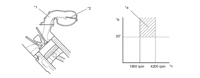
| *1 | Intake Air Surge Tank Assembly | *2 | Intake Air Control Valve Assembly |
| *a | Intake Air Control Valve Assembly Close | *b | Throttle Valve Opening Angle |
| *c | Engine Speed | - | - |
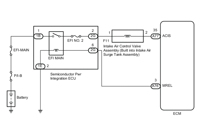
WIRING DIAGRAM
CAUTION / NOTICE / HINT
Note
Inspect the fuses for circuits related to this system before performing the following procedure.
PROCEDURE
-
PERFORM ACTIVE TEST USING GTS (ACTIVATE THE VSV FOR INTAKE CONTROL)
-
Connect the GTS to the DLC3.
-
Turn the engine switch on (IG).
-
Turn the GTS on.
-
Enter the following menus: Powertrain / Engine and ECT / Active Test / Activate the VSV for Intake Control.
Powertrain > Engine > Active TestTester Display Activate the VSV for Intake Control -
Check if operating noise can be heard when operating the intake air control valve assembly using the GTS.
OK Operating noise can be heard. Result Proceed to OK NG
OK 
PROCEED TO NEXT SUSPECTED AREA SHOWN IN PROBLEM SYMPTOMS TABLE Click here
NG 
-
-
INSPECT INTAKE AIR SURGE TANK ASSEMBLY (INTAKE AIR CONTROL VALVE ASSEMBLY OPERATION)
-
Inspect the intake air surge tank assembly (intake air control valve assembly).
Result Proceed to OK NG
NG
REPLACE INTAKE AIR SURGE TANK ASSEMBLY Click here
OK
-
-
CHECK TERMINAL VOLTAGE (POWER SOURCE OF INTAKE AIR CONTROL VALVE ASSEMBLY)
-
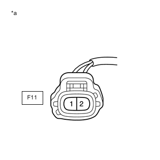
*a Front view of wire harness connector
(to Intake Air Control Valve Assembly)
Disconnect the intake air control valve assembly connector.
-
Turn the engine switch on (IG).
-
Measure the voltage according to the value(s) in the table below.
Standard Voltage Tester Connection Condition Specified Condition F11-2 - Body ground Engine switch on (IG) 11 to 14 V Result Proceed to OK NG
NG 
CHECK HARNESS AND CONNECTOR (SEMICONDUCTOR PWR INTEGRATION ECU - INTAKE AIR CONTROL VALVE ASSEMBLY) Click here
OK
-
-
CHECK HARNESS AND CONNECTOR (INTAKE AIR CONTROL VALVE ASSEMBLY - ECM)
-
Disconnect the intake air control valve assembly connector.
-
Disconnect the ECM connector.
-
Measure the resistance according to the value(s) in the table below.
Standard Resistance Tester Connection Condition Specified Condition F11-2 - A77-35 (ACIS) Always Below 1 Ω F11-2 or A77-35 (ACIS) - Body ground Always 10 kΩ or higher Result Proceed to OK NG
OK
REPLACE ECM Click here
NG
REPAIR OR REPLACE HARNESS OR CONNECTOR
-
-
CHECK HARNESS AND CONNECTOR (SEMICONDUCTOR PWR INTEGRATION ECU - INTAKE AIR CONTROL VALVE ASSEMBLY)
-
Disconnect the semiconductor pwr integration ECU connector.
-
Disconnect the intake air control valve assembly connector.
-
Measure the resistance according to the value(s) in the table below.
Standard Resistance Tester Connection Condition Specified Condition 2G-2 - F11-1 Always Below 1 Ω 2G-2 or F11-1 - Body ground Always 10 kΩ or higher Result Proceed to OK NG
OK
GO TO ECM POWER SOURCE CIRCUIT Click here
NG
REPAIR OR REPLACE HARNESS OR CONNECTOR
-