CAMSHAFT INSTALLATION

CAUTION / NOTICE / HINT
Tech Tips
Perform "Inspection After Repair" after replacing the camshaft, No. 2 camshaft, camshaft timing gear assembly or camshaft timing exhaust gear assembly.
Click here (w/ Canister Pump Module)
Click here (w/o Canister Pump Module)
PROCEDURE
-
INSTALL NO. 2 CAMSHAFT BEARING
-
INSTALL NO. 1 CAMSHAFT BEARING
-
INSTALL OIL CONTROL VALVE FILTER
-
INSTALL CAMSHAFT TIMING EXHAUST GEAR ASSEMBLY
Tech Tips
Perform "Inspection After Repair" after replacing the camshaft timing exhaust gear assembly.
Click here (w/ Canister Pump Module)
Click here (w/o Canister Pump Module)
-
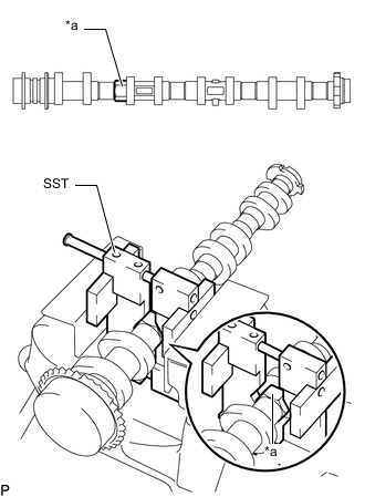
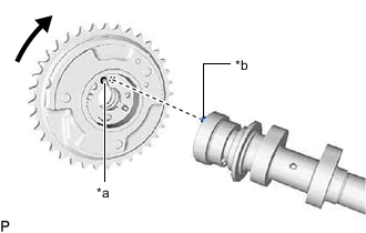
*a Hexagonal Portion Using SST, grip the hexagonal portion, and then secure the SST and No. 2 camshaft in a vise as shown in the illustration.
- SST
- 09212-31010
Note
-
Do not damage the No. 2 camshaft.
-
Never grip areas other than the hexagonal portion, as this may cause damage.
-
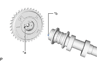
*a Knock Pin Hole *b Knock Pin Align the knock pin of the No. 2 camshaft with the knock pin hole of the camshaft timing exhaust gear assembly and attach the camshaft timing exhaust gear assembly to the No. 2 camshaft.
Note
Do not forcefully press the camshaft timing exhaust gear assembly. Otherwise, the tip of knock pin of the No. 2 camshaft may damage the seal surface of the camshaft timing exhaust gear assembly, leading to poor sealing.
-
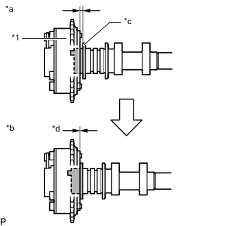
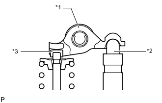
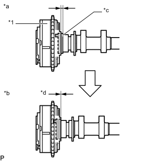
*1 Camshaft Timing Exhaust Gear Assembly *a Incorrect *b Correct *c No. 2 Camshaft Flange *d No Clearance Check that there is no clearance between the camshaft timing exhaust gear assembly and No. 2 camshaft flange.
-
Secure the No. 2 camshaft in place by hand, and then install the bolt of the camshaft timing exhaust gear assembly by hand.
-
Tighten the bolt.
- Torque:
- 85 N*m { 867 kgf*cm, 63 ft.*lbf }
Note
-
Do not damage the No. 2 camshaft and camshaft timing exhaust gear assembly.
-
Do not disassemble the camshaft timing exhaust gear assembly.
-
-
SET NO. 1 CYLINDER TO TDC/COMPRESSION
-
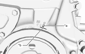
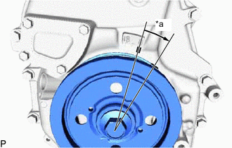
*a Timing Mark "0" *b Timing Mark (Groove) Turn the crankshaft until the timing mark (groove) of the crankshaft pulley assembly and the timing mark "0" of the timing chain cover assembly are aligned.
-
-
INSTALL NO. 2 CAMSHAFT
Note
When turning the No. 2 camshaft with the chain sub-assembly removed, take care to prevent the piston and valve from contacting and damaging the part.
Tech Tips
Perform "Inspection After Repair" after replacing the No. 2 camshaft.
Click here (w/ Canister Pump Module)
Click here (w/o Canister Pump Module)
-
*1 No. 1 Valve Rocker Arm Sub-assembly *2 Valve Lash Adjuster Assembly *3 Valve Stem Cap Check that the No. 1 valve rocker arm sub-assemblies are installed as shown in the illustration.
-
Clean the camshaft journals.
-
Apply a light coat of engine oil to the No. 2 camshaft journals and camshaft housing sub-assembly.
-
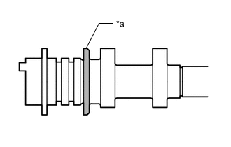
*a Thrust Surface Clean the thrust surface of the No. 2 camshaft and apply engine oil.
-
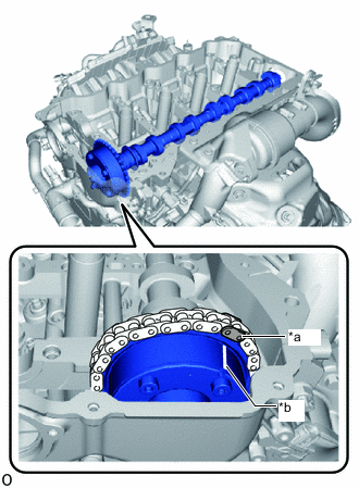
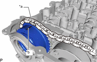
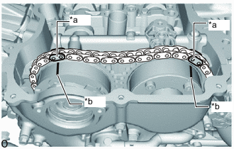
*a Paint Mark *b Timing Mark (Groove) Align the paint mark of the chain sub-assembly that was put on when the chain sub-assembly was removed and the timing mark (groove) of the camshaft timing exhaust gear assembly. Then install the No. 2 camshaft and camshaft timing exhaust gear assembly.
-
-
INSTALL CAMSHAFT TIMING GEAR ASSEMBLY
Tech Tips
Perform "Inspection After Repair" after replacing the camshaft timing gear assembly.
Click here (w/ Canister Pump Module)
Click here (w/o Canister Pump Module)
-
*a Paint Mark *b Timing Mark (Groove) Align the paint mark of the chain sub-assembly that was put on when the chain sub-assembly was removed and the timing mark (groove) of the camshaft timing gear assembly. Then install the camshaft timing gear assembly.
Note
Do not disassemble the camshaft timing gear assembly.
-
-
INSTALL CAMSHAFT
Note
When turning the camshaft with the chain sub-assembly removed, take care to prevent the piston and valve from contacting and damaging the part.
Tech Tips
Perform "Inspection After Repair" after replacing the camshaft.
Click here (w/ Canister Pump Module)
Click here (w/o Canister Pump Module)
-
*1 No. 1 Valve Rocker Arm Sub-assembly *2 Valve Lash Adjuster Assembly *3 Valve Stem Cap Check that the No. 1 valve rocker arm sub-assemblies are installed as shown in the illustration.
-
Clean the camshaft journals.
-
Apply a light coat of engine oil to the camshaft journals and camshaft housing sub-assembly.
-
*a Thrust Surface Clean the thrust surface of the camshaft and apply engine oil.
-
*a Knock Pin Hole *b Knock Pin Put the camshaft timing gear assembly and camshaft together with the knock pin of the knock pin hole.
-
Turn the camshaft timing gear assembly clockwise while pushing it gently toward the camshaft. When the knock pin fits into the knock pin hole, push to ensure a good fit.
Note
Do not forcefully press the camshaft timing gear assembly. Otherwise, the tip of knock pin of the camshaft may damage the seal surface of the camshaft timing gear assembly, leading to poor sealing.
-
*1 Camshaft Timing Gear Assembly *a Incorrect *b Correct *c Portion A of Camshaft *d No Clearance Check that there is no clearance between the camshaft timing gear assembly and portion A of the camshaft indicated in the illustration.
-
-
TEMPORARILY INSTALL CAMSHAFT TIMING GEAR BOLT
Note
There are different types of camshaft timing gear bolts. Make sure to check the identification mark on the bolt and use the specified torque value for the bolt when tightening.
Identification Mark Type Identification Mark A A B C 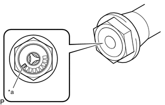
*a Identification Mark
-
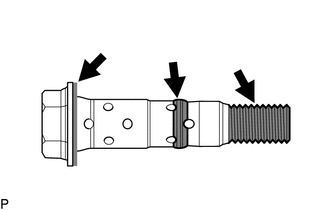
Apply engine oil to the areas of the camshaft timing gear bolt indicated in the illustration.
-
Temporarily install the camshaft timing gear bolt to the camshaft.
Tech Tips
When temporarily installing the camshaft timing gear bolt, make sure that it is screwed in approximately 3 threads.
-
-
INSTALL CAMSHAFT BEARING CAP
-
*1 No. 1 Camshaft Bearing Cap *2 No. 2 Camshaft Bearing Cap *3 No. 3 Camshaft Bearing Cap *4 No. 4 Camshaft Bearing Cap Place the No. 1, No. 2, No. 3 and No. 4 camshaft bearing caps to the camshaft housing sub-assembly.
-
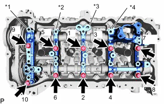
Install the 10 camshaft bearing cap bolts in the order shown in the illustration.
- Torque:
- 27 N*m { 275 kgf*cm, 20 ft.*lbf }
-
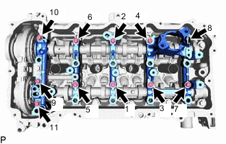
Install the 11 camshaft bearing cap bolts in the order shown in the illustration.
- Torque:
- 16 N*m { 163 kgf*cm, 12 ft.*lbf }
-
-
TIGHTEN CAMSHAFT TIMING GEAR BOLT
-
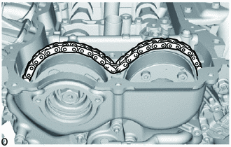
Check that the chain sub-assembly is loose as shown in the illustration.
-
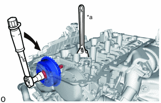
*a Hold 
Turn Use a wrench to hold the hexagonal portion of the camshaft.
-
Tighten the camshaft timing gear bolt.
- Torque:
- Type A
- 120 N*m { 1224 kgf*cm, 89 ft.*lbf }
- Type B
- 95 N*m { 969 kgf*cm, 70 ft.*lbf }
Note
Be careful not to damage the camshaft housing sub-assembly or spark plug tube with the wrench.
-
*a Paint Mark *b Timing Mark (Groove) Check that each timing mark (groove) of the camshaft timing gear assembly and camshaft timing exhaust gear assembly are aligned with each paint mark located as shown in the illustration.
-
-
ADD ENGINE OIL
-
INSTALL TIMING CHAIN GUIDE
-
INSTALL NO. 1 CHAIN TENSIONER ASSEMBLY
-
*a Approximately 15° Turn the crankshaft approximately 15° clockwise.
-
Temporarily install a new gasket and the No. 1 chain tensioner assembly to the cylinder block sub-assembly with the nut and bolt.
Note
Make sure not to drop the gasket inside the timing chain cover assembly.
-
Tighten the nut and bolt.
- Torque:
- 10 N*m { 102 kgf*cm, 7 ft.*lbf }
-
Remove the pin from the stopper plate.
-
-
CHECK NO. 1 CYLINDER TO TDC/COMPRESSION
-
Turn the crankshaft until the timing mark (groove) of the crankshaft pulley assembly and the timing mark "0" of the timing chain cover assembly are aligned.
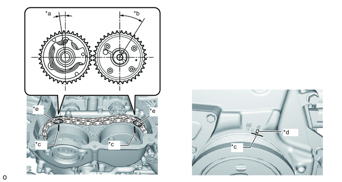
*a Approximately 7° *b Approximately 32° *c Timing Mark (Groove) *d Timing Mark "0" *e Paint Mark - - -
Check that each timing mark (groove) of the camshaft timing gear assembly and camshaft timing exhaust gear assembly are aligned with each paint mark located as shown in the illustration.
-
-
INSTALL TIMING CHAIN COVER PLATE
-
INSTALL CAM TIMING OIL CONTROL SOLENOID ASSEMBLY
-
INSTALL VACUUM PUMP ASSEMBLY
-
INSTALL CAMSHAFT BEARING CAP OIL HOLE GASKET
-
Apply a light coat of engine oil to a new gasket and new camshaft bearing cap oil hole gasket.
-
Install the gasket to the No. 2 camshaft bearing cap.
-
Install the camshaft bearing cap oil hole gasket to the No. 1 camshaft bearing cap.
-
-
INSTALL CYLINDER HEAD COVER GASKET
-
Install a new cylinder head cover gasket and new No. 2 cylinder head cover gasket to the cylinder head cover sub-assembly.
-
-
INSTALL CYLINDER HEAD COVER SUB-ASSEMBLY
-
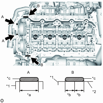
*1 Timing Chain Cover Assembly *2 Camshaft Housing Sub-assembly *a Application Width: 8.0 mm (0.315 in.) *b Application Width: 5.0 mm (0.197 in.) *c Seal Diameter: 2.0 to 3.0 mm (0.0787 to 0.118 in.) Seal Packing Apply seal packing as shown in the illustration.
Seal packing Toyota Genuine Seal Packing Black, Three Bond 1207B or equivalent Standard seal diameter 2.0 to 3.0 mm (0.0787 to 0.118 in.) Note
-
Remove any oil from the contact surface.
-
Install the cylinder head cover sub-assembly within 3 minutes and tighten the bolts within 15 minutes after applying seal packing.
-
Do not add engine oil for at least 2 hours after installation.
-
Do not start the engine within 2 hours after installation.
-
-
Apply a light coat of engine oil to the 2 camshaft position sensors.
-
Temporarily install the cylinder head cover sub-assembly and the 2 camshaft position sensors with the 21 bolts.
-
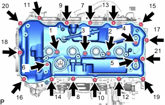
Tighten the 21 bolts in the order shown in the illustration.
- Torque:
- 10 N*m { 102 kgf*cm, 7 ft.*lbf }
-
-
INSTALL NO. 3 VENTILATION HOSE
-
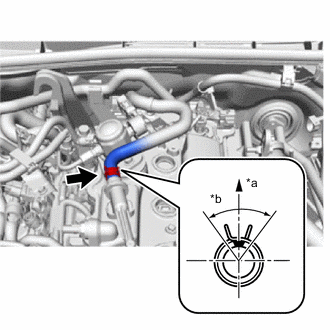
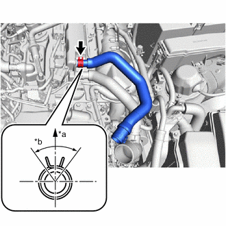
*a Upper Side *b 90° Connect the No. 3 ventilation hose with the clip as shown in the illustration.
Tech Tips
Install the clip so that it is positioned as shown in the illustration.
-
-
INSTALL NO. 1 TURBO WATER PIPE
-
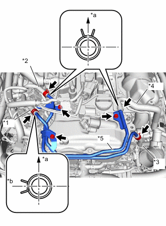
*1 No. 1 Turbo Water By-pass Hose *2 No. 2 Turbo Water By-pass Hose *3 No. 3 Turbo Water By-pass Hose *4 No. 4 Turbo Water By-pass Hose *5 No. 1 Turbo Water Pipe *a Upper Side *b RH Side Install the No. 1 turbo water pipe to the cylinder head cover sub-assembly with the 3 bolts.
- Torque:
- 10 N*m { 102 kgf*cm, 7 ft.*lbf }
-
Connect the No. 1, No. 2, No. 3 and No. 4 turbo water by-pass hoses with the 4 clips as shown in the illustration.
Tech Tips
Install the clips so that they are positioned as shown in the illustration.
-
-
CONNECT ENGINE WIRE
-
Connect the engine wire to the cylinder head cover sub-assembly with the bolt.
- Torque:
- 10 N*m { 102 kgf*cm, 7 ft.*lbf }
-
Attach the clamp and connect the No. 3 ventilation hose to the engine wire.
-
Connect the connector to the air fuel ratio sensor.
-
Connect the 2 connectors to the 2 camshaft position sensors.
-
-
INSTALL IGNITION COIL ASSEMBLY
-
INSTALL NO. 4 VENTILATION HOSE
-
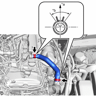
*a Upper Side *b 90° Install the No. 4 ventilation hose with the 2 clips as shown in the illustration.
Tech Tips
Install the clips so that they are positioned as shown in the illustration.
-
-
CONNECT VENTILATION HOSE
-
*a Upper Side *b 90° Connect the ventilation hose with the clip as shown in the illustration.
Tech Tips
Install the clip so that it is positioned as shown in the illustration.
-
Attach the clamp.
-
-
INSTALL FUEL PUMP ASSEMBLY (for High Pressure)
-
INSTALL FAN SHROUD
-
INSPECT FOR OIL LEAK