CAMSHAFT REMOVAL

PROCEDURE
-
REMOVE FAN SHROUD
-
REMOVE FUEL PUMP ASSEMBLY (for High Pressure)
-
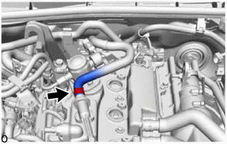
REMOVE VENTILATION HOSE
-
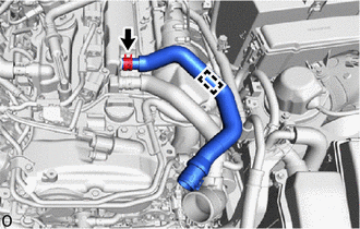
Detach the clamp.
-
Slide the clip and remove the ventilation hose from the cylinder head cover sub-assembly.
-
-
REMOVE NO. 4 VENTILATION HOSE
-
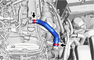
Slide the 2 clips and remove the No. 4 ventilation hose from the cylinder head cover sub-assembly and inlet compressor elbow.
-
-
REMOVE IGNITION COIL ASSEMBLY
-
REMOVE CAMSHAFT POSITION SENSOR (for Exhaust Side)
-
REMOVE CAMSHAFT POSITION SENSOR (for Intake Side)
-
DISCONNECT ENGINE WIRE
-
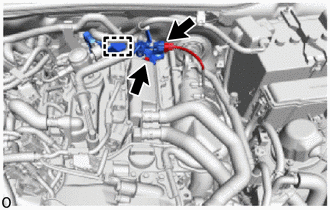
Detach the clamp and disconnect the No. 3 ventilation hose from the engine wire.
-
Disconnect the air fuel ratio sensor connector.
-
Remove the bolt and disconnect the engine wire from the cylinder head cover sub-assembly.
-
-
REMOVE NO. 1 TURBO WATER PIPE
-
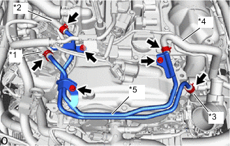
*1 No. 1 Turbo Water By-pass Hose *2 No. 2 Turbo Water By-pass Hose *3 No. 3 Turbo Water By-pass Hose *4 No. 4 Turbo Water By-pass Hose *5 No. 1 Turbo Water Pipe Slide the 4 clips and disconnect the No. 1, No. 2, No. 3 and No. 4 turbo water by-pass hoses.
-
Remove the 3 bolts and No. 1 turbo water pipe.
-
-
REMOVE NO. 3 VENTILATION HOSE
-
Slide the clip and disconnect the No. 3 ventilation hose from the cylinder head cover sub-assembly.
-
-
REMOVE CYLINDER HEAD COVER SUB-ASSEMBLY
-
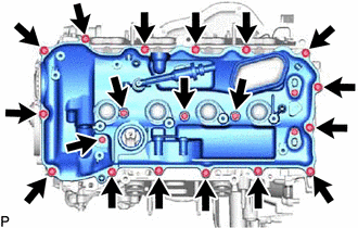
Remove the 19 bolts and cylinder head cover sub-assembly from the camshaft housing sub-assembly.
-
-
REMOVE CYLINDER HEAD COVER GASKET
-
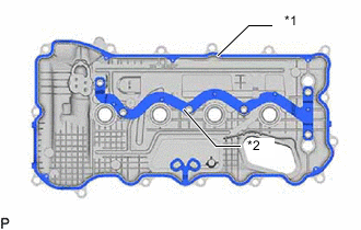
*1 Cylinder Head Cover Gasket *2 No. 2 Cylinder Head Cover Gasket Remove the cylinder head cover gasket and No. 2 cylinder head cover gasket from the cylinder head cover sub-assembly.
-
-
REMOVE CAMSHAFT BEARING CAP OIL HOLE GASKET
-
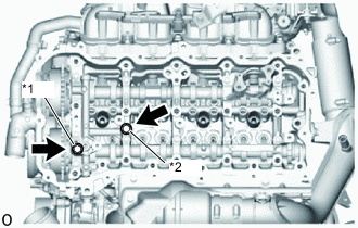
*1 Camshaft Bearing Cap Oil Hole Gasket *2 Gasket Remove the camshaft bearing cap oil hole gasket from the No. 1 camshaft bearing cap.
-
Remove the gasket from the No. 2 camshaft bearing cap.
-
-
REMOVE VACUUM PUMP ASSEMBLY
-
REMOVE CAM TIMING OIL CONTROL SOLENOID ASSEMBLY
-
SET NO. 1 CYLINDER TO TDC/COMPRESSION
-
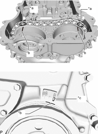
*a Paint Mark *b Timing Mark (Groove) *c Timing Mark "0" Turn the crankshaft until the timing mark (groove) of the crankshaft pulley assembly and the timing mark "0" of the timing chain cover assembly are aligned.
-
Check that each timing mark of the camshaft timing gear assembly and camshaft timing exhaust gear assembly are located as shown in the illustration. If not, turn the crankshaft 1 revolution (360°) to align the timing marks as shown in the illustration.
-
Place paint marks on the chain sub-assembly in alignment with the timing marks on the camshaft timing gear assembly and camshaft timing exhaust gear assembly.
-
-
REMOVE TIMING CHAIN COVER PLATE
-
REMOVE NO. 1 CHAIN TENSIONER ASSEMBLY
-
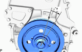
*a Approximately 15° Turn the crankshaft approximately 15° clockwise.
-
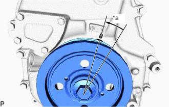
*a Approximately 15° Turn the crankshaft approximately 15° counterclockwise.
-
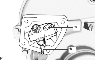
*a Stopper Plate *b Pin Align the holes of the stopper plate and No. 1 chain tensioner assembly, and insert a pin into the stopper plate hole to lock the No. 1 chain tensioner assembly.
-
*a Approximately 15° Turn the crankshaft approximately 15° clockwise.
-
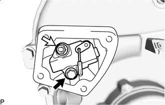

Bolt 
Nut Remove the bolt and nut, and then remove the No. 1 chain tensioner assembly and gasket from the cylinder block sub-assembly.
Note
Make sure not to drop the gasket inside the timing chain cover assembly.
-
*a Approximately 15° Turn the crankshaft approximately 15° counterclockwise.
-
-
REMOVE TIMING CHAIN GUIDE
-
REMOVE CAMSHAFT TIMING GEAR BOLT
-
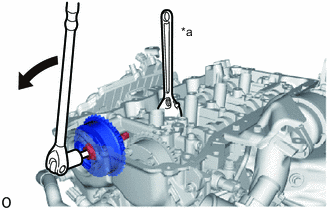
*a Hold Turn Hold the hexagonal portion of the camshaft with a wrench and remove the camshaft timing gear bolt from the camshaft.
Note
Be careful not to damage the camshaft housing sub-assembly or spark plug tube with the wrench.
-
-
REMOVE CAMSHAFT BEARING CAP
-
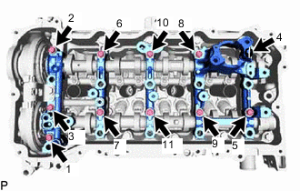
Using several steps, remove the 11 camshaft bearing cap bolts in the sequence shown in the illustration.
-
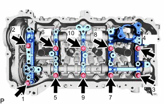
Using several steps, remove the 10 camshaft bearing cap bolts in the sequence shown in the illustration.
Note
Make sure to loosen the camshaft bearing cap bolts evenly while holding the camshaft horizontally.
-
Remove the No. 1, No. 2, No. 3 and No. 4 camshaft bearing caps from the camshaft housing sub-assembly.
Tech Tips
Arrange the removed parts in the correct order.
-
-
REMOVE CAMSHAFT
-
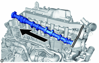
Raise the camshaft as shown in the illustration to remove it from the camshaft timing gear assembly.
-
-
REMOVE CAMSHAFT TIMING GEAR ASSEMBLY
-
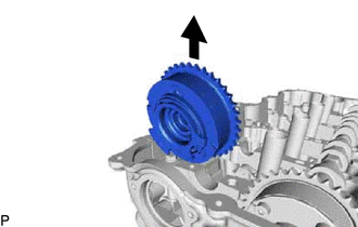
Remove the camshaft timing gear assembly.
Note
Do not disassemble the camshaft timing gear assembly.
-
-
REMOVE NO. 2 CAMSHAFT
-
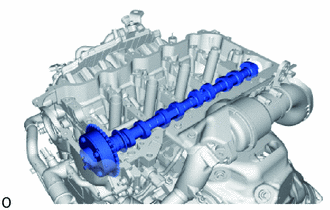
Remove the No. 2 camshaft from the camshaft housing sub-assembly.
-
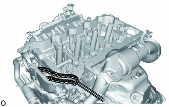
Suspend the chain sub-assembly with a string or equivalent as shown in the illustration.
Note
Be careful not to drop the chain sub-assembly inside the timing chain cover assembly.
-
-
REMOVE CAMSHAFT TIMING EXHAUST GEAR ASSEMBLY
-
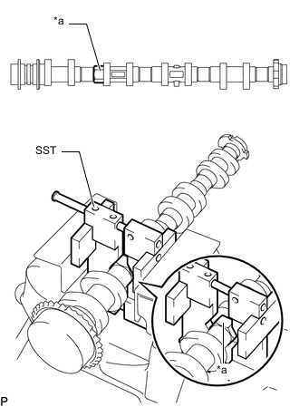
*a Hexagonal Portion Using SST, grip the hexagonal portion, and then secure the SST and No. 2 camshaft in a vise as shown in the illustration.
- SST
- 09212-31010
Note
-
Do not damage the No. 2 camshaft.
-
Never grip areas other than the hexagonal portion, as this may cause damage.
-
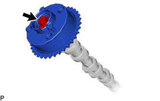
Remove the bolt and camshaft timing exhaust gear assembly from the No. 2 camshaft.
Note
-
Be careful not to damage the No. 2 camshaft and camshaft timing exhaust gear assembly.
-
Do not disassemble the camshaft timing exhaust gear assembly.
-
-
-
REMOVE OIL CONTROL VALVE FILTER
-
REMOVE NO. 1 CAMSHAFT BEARING
-
REMOVE NO. 2 CAMSHAFT BEARING
-
INSPECT CAMSHAFT TIMING EXHAUST GEAR ASSEMBLY