CAMSHAFT POSITION SENSOR INSTALLATION
PROCEDURE
-
INSTALL VVT SENSOR (for Intake Side of Bank 2)
-
Apply a light coat of engine oil to the O-ring of the VVT sensor.
Note
If reusing the VVT sensor, be sure to inspect the O-ring.
-
Clean the bolt and bolt hole.
-
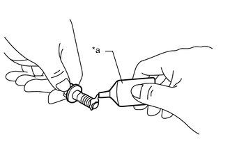
*a Adhesive Apply adhesive to 2 or 3 threads at the end of the bolt.
Adhesive Toyota Genuine Adhesive 1324, Three Bond 1324 or equivalent -
Install the VVT sensor to the cylinder head cover sub-assembly LH with the bolt.
- Torque:
- 10 N*m { 102 kgf*cm, 7 ft.*lbf }
Note
-
If the VVT sensor has been struck or dropped, replace it.
-
Make sure that the O-ring is not cracked or moved out of place when installing the VVT sensor.
-
-
INSTALL VVT SENSOR (for Exhaust Side of Bank 2)
-
Apply a light coat of engine oil to the O-ring of the VVT sensor.
Note
If reusing the VVT sensor, be sure to inspect the O-ring.
-
Clean the bolt and bolt hole.
-
*a Adhesive Apply adhesive to 2 or 3 threads at the end of the bolt.
Adhesive Toyota Genuine Adhesive 1324, Three Bond 1324 or equivalent -
Install the VVT sensor to the cylinder head cover sub-assembly LH with the bolt.
- Torque:
- 10 N*m { 102 kgf*cm, 7 ft.*lbf }
Note
-
If the VVT sensor has been struck or dropped, replace it.
-
Make sure that the O-ring is not cracked or moved out of place when installing the VVT sensor.
-
-
CONNECT ENGINE WIRE
-
Connect the 2 VVT sensor connectors and 2 ignition coil assembly connectors.
-
Connect the engine wire to the cylinder head cover sub-assembly LH with the 2 nuts.
- Torque:
- 10 N*m { 102 kgf*cm, 7 ft.*lbf }
-
Engage the 3 clamps.
-
Connect the engine wire to the timing chain cover assembly with the bolt.
- Torque:
- 10 N*m { 102 kgf*cm, 7 ft.*lbf }
-
Connect the 2 camshaft timing oil control solenoid assembly connectors and water inlet with thermostat sub-assembly connector.
-
Engage the clamp.
-
-
INSTALL VVT SENSOR (for Intake Side of Bank 1)
-
Apply a light coat of engine oil to the O-ring of the VVT sensor.
Note
If reusing the VVT sensor, be sure to inspect the O-ring.
-
Clean the bolt and bolt hole.
-
*a Adhesive Apply adhesive to 2 or 3 threads at the end of the bolt.
Adhesive Toyota Genuine Adhesive 1324, Three Bond 1324 or equivalent -
Install the VVT sensor to the cylinder head cover sub-assembly with the bolt.
- Torque:
- 10 N*m { 102 kgf*cm, 7 ft.*lbf }
Note
-
If the VVT sensor has been struck or dropped, replace it.
-
Make sure that the O-ring is not cracked or moved out of place when installing the VVT sensor.
-
Connect the VVT sensor connector.
-
-
INSTALL VVT SENSOR (for Exhaust Side of Bank 1)
-
Apply a light coat of engine oil to the O-ring of the VVT sensor.
Note
If reusing the VVT sensor, be sure to inspect the O-ring.
-
Clean the bolt and bolt hole.
-
*a Adhesive Apply adhesive to 2 or 3 threads at the end of the bolt.
Adhesive Toyota Genuine Adhesive 1324, Three Bond 1324 or equivalent -
Install the VVT sensor to the cylinder head cover sub-assembly with the bolt.
- Torque:
- 10 N*m { 102 kgf*cm, 7 ft.*lbf }
Note
-
If the VVT sensor has been struck or dropped, replace it.
-
Make sure that the O-ring is not cracked or moved out of place when installing the VVT sensor.
-
Connect the VVT sensor connector.
-
-
INSTALL AIR CLEANER CAP WITH AIR CLEANER HOSE
-
INSTALL V-BANK COVER SUB-ASSEMBLY