СИСТЕМА ЗАРЯДКИ АККУМУЛЯТОРНОЙ БАТАРЕИ, Diagnostic DTC:P161A

| DTC Code | DTC Name |
|---|---|
| P161A | LIN Communication Error with Alternator |
DESCRIPTION
The generator control ECU assembly and generator assembly detect reception errors respectively. The generator assembly reception error detected by the generator assembly is sent to the generator control ECU assembly via LIN communication. If an error occurs in the generator control ECU assembly or generator assembly, the generator control ECU assembly determines there is a LIN communication error and stores this DTC.
| DTC No. | Detection Item | DTC Detection Condition | Trouble Area | MIL | Memory |
|---|---|---|---|---|---|
| P161A | LIN Communication Error with Alternator | A reception error in the generator control ECU assembly or generator assembly continues for approximately 17 minutes or more with the ignition switch ON (1 trip detection logic) |
|
Come on | DTC stored |
WIRING DIAGRAM
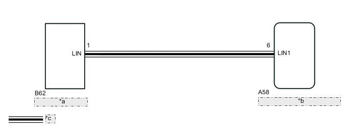
| *a | Generator Assembly |
| *b | Generator Control ECU Assembly (Battery Current Sensor) |
| *c | LIN Communication Line |
PROCEDURE
-
CHECK CHARGING SYSTEM
-
Check the charging system.
Result Result OK NG
NG 
REPAIR OR REPLACE CHARGING SYSTEM
OK 
-
-
CHECK HARNESS AND CONNECTOR (GENERATOR CONTROL ECU ASSEMBLY (BATTERY CURRENT SENSOR) - GENERATOR ASSEMBLY)
-
Disconnect the A58 generator control ECU assembly connector.
-
Disconnect the B62 generator assembly connector.
-
Measure the resistance according to the value(s) in the table below.
Standard Resistance (Check for Open) Tester Connection Condition Specified Condition A58-6 (LIN1) - B62-1 (LIN) Always Below 1 Ω Standard Resistance (Check for Short) Tester Connection Condition Specified Condition A58-6 (LIN1) or B62-1 (LIN) - Body ground Ignition switch off
(while LIN communication is stopped)
10 kΩ or higher Result Result OK NG
NG
REPAIR OR REPLACE HARNESS OR CONNECTOR
OK
-
-
INSPECT GENERATOR ASSEMBLY
-
Inspect the generator assembly.
Result Result OK NG
OK
REPLACE GENERATOR CONTROL ECU ASSEMBLY (BATTERY CURRENT SENSOR) Click here
NG
REPLACE GENERATOR ASSEMBLY Click here
-