СИСТЕМА ЗАПУСКА И ОСТАНОВА (для моделей с 2WW) Neutral Position Switch Circuit
DESCRIPTION
The neutral position sensor (neutral position switch) detects whether the shift lever is in neutral. When the shift lever in any position other than neutral, stop and start control is prohibited
WIRING DIAGRAM
PROCEDURE
-
READ VALUE USING GTS (NEUTRAL SWITCH)
-
Connect the GTS to the DLC3.
-
Turn the ignition switch to ON.
-
Turn the GTS on.
-
Enter the following menus: Powertrain / Stop and Start / Data List / Neutral Switch.
Powertrain > Stop and Start > Data ListTester Display Neutral Switch -
Read the value when the shift lever is in neutral and any other position
OK Tester Display Condition Normal Condition Neutral Switch Shift lever is in neutral ON Shift lever is in any position other than neutral OFF Result Proceed to OK NG
OK 
GO TO PROCEED TO NEXT SUSPECTED AREA SHOWN IN PROBLEM SYMPTOMS TABLE Click here
NG 
-
-
CHECK HARNESS AND CONNECTOR (ENGINE STOP AND START ECU - NEUTRAL POSITION SENSOR (NEUTRAL POSITION SWITCH))
-
Disconnect the A66 engine stop and start ECU connector.
-
Disconnect the C16 neutral position sensor (neutral position switch) connector.
-
Measure the resistance according to the value(s) in the table below.
Standard Resistance Tester Connection Condition Specified Condition A66-26 (TMVC) - C16-1 (W1) Always Below 1 Ω A66-25 (TME2) - C16-3 (F+) Always Below 1 Ω A66-8 (TMN) - C16-2 (TMN) Always Below 1 Ω A66-26 (TMVC) - Body ground Always 10 kΩ or higher C16-1 (W1) - Body ground Always 10 kΩ or higher A66-25 (TME2) - Body ground Always 10 kΩ or higher C16-3 (F+) - Body ground Always 10 kΩ or higher A66-8 (TMN) - Body ground Always 10 kΩ or higher C16-2 (TMN) - Body ground Always 10 kΩ or higher Result Proceed to OK NG
NG
REPAIR OR REPLACE HARNESS OR CONNECTOR
OK
-
-
CHECK ENGINE STOP AND START ECU (TMN TERMINAL VOLTAGE)
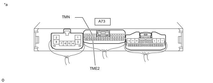
*a Component with harness connected
(Engine Stop and Start ECU)
- -
-
Measure the voltage according to the value(s) in the table below.
Standard Voltage Tester Connection Condition Specified Condition A66-8 (TMN) - A66-25 (TME2) Ignition switch ON, shift lever in neutral 2.7 to 4.3 V Ignition switch ON, shift lever in any position other than neutral 0.7 to 1.9 V Result Proceed to OK NG
OK
GO TO PROCEED TO NEXT SUSPECTED AREA SHOWN IN PROBLEM SYMPTOMS TABLE Click here
NG
REPLACE NEUTRAL POSITION SWITCH Click here
-