СТАРТЕР (для моделей с системой запуска и останова) ПРОВЕРКА
CAUTION / NOTICE / HINT
Tech Tips
When replacing the starter assembly, it is necessary to replace the ST NO. 1 relay and ST NO. 2 relay as well.
PROCEDURE
-
INSPECT STARTER ASSEMBLY (for CVT)
CAUTION:
As a large electric current passes through the cable during this inspection, a thick cable must be used. If not, the cable may become hot and cause injury.
Note
Perform each of the following tests within 3 to 5 seconds to prevent the coil from burning out.
-
Perform a no-load performance test.
-
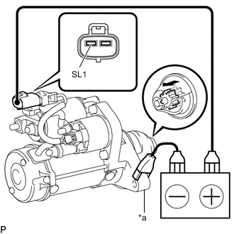
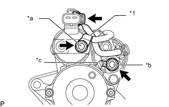
*a Starter Body Connect the positive (+) lead to terminal SL1.
-
Connect the negative (-) lead to the starter body and check that the clutch pinion gear moves outward.
Note
If the positive (+) and negative (-) leads are connected incorrectly, the IC inside of the starter inrush current reduction relay will be damaged. Be sure to connect them correctly.
-
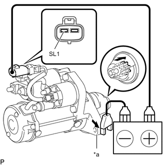
*a Starter Body With the clutch pinion gear in the outward position, disconnect the negative (-) lead and check that the clutch pinion gear returns inward.
-
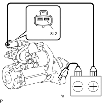
*a Starter Body Connect the positive (+) lead to terminal SL2 of the connector and the negative (-) lead to the starter body. Check that a clicking sound is heard from the starter motor.
-
Hold the starter assembly in a vise between aluminum plates.
Note
Ensure that the starter assembly is secured in the vise to prevent it from falling out.
-
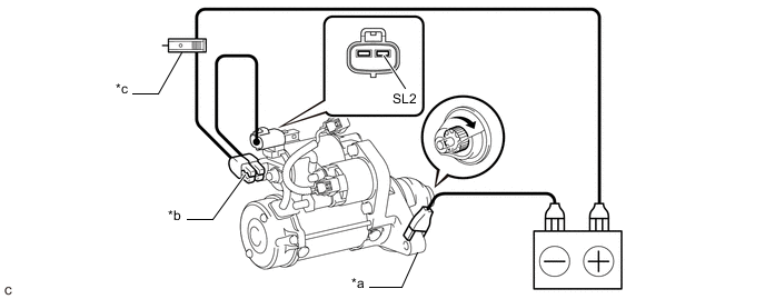
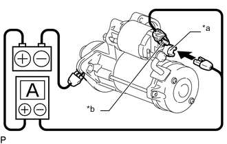
Connect the battery and an ammeter to the starter assembly as shown in the illustration.
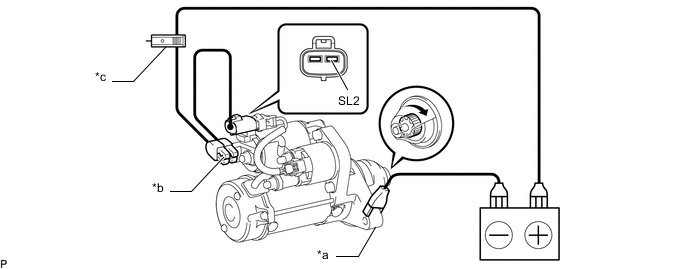
*a Starter Body *b Terminal 30 *c AC/DC 400 A Probe - - -
Connect terminal SL2 and measure the current after the ammeter reading has stabilized.
Standard Current Tester Connection Condition Specified Condition Battery positive (+) terminal - Terminal 30 - Terminal SL2 11.5 V Below 130 A Tech Tips
If the starter assembly does not operate when terminal SL2 is connected, perform the following steps (*1) through (*5).
-
*1 Wire Harness *a Terminal C *b Terminal M *c Lead Wire Disconnect the repair service starter kit connector. (*1)
-
Remove the nut and disconnect the wire harness from terminal C. (*2)
-
Remove the nut and disconnect the lead wire from terminal M. (*3)
-
Connect the lead wire to terminal C with the nut. (*4)
- Torque:
- 9.0 N*m { 92 kgf*cm, 80 in.*lbf }
-
Connect the battery and an ammeter to the starter assembly as shown in the illustration. (*5)
*a Starter Body *b Terminal 30 *c AC/DC 400 A Probe - - If the starter assembly does not operate, replace the repair service starter kit.
-
-
-
INSPECT STARTER ASSEMBLY (for Manual Transaxle)
CAUTION:
As a large electric current passes through the cable during this inspection, a thick cable must be used. If not, the cable may be hot and cause injury.
Note
These tests must be performed within 3 to 5 seconds to avoid burning out the coil.
-
Perform the pull-in test.
-
Remove the nut and disconnect the lead wire from terminal C.
-
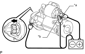
*a Terminal 50 *b Terminal C Connect the battery to the magnet starter switch assembly as shown in the illustration. Check that the clutch pinion gear extends.
If the clutch pinion gear does not move, replace the magnet starter switch assembly.
-
-
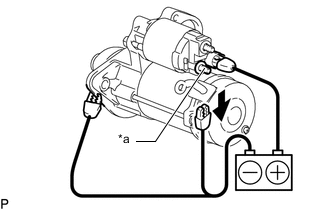
*a Terminal C 
Disconnect Perform the holding test.
-
Maintain the battery connections of the pull-in test above, but disconnect the negative (-) lead from terminal C. Check that the pinion gear remains extended.
If the clutch pinion gear returns inward, replace the magnet starter switch assembly.
-
-

Disconnect 
Returns Inward Check the clutch pinion gear return.
-
Disconnect the negative (-) lead from the starter body. Check that the clutch pinion gear returns.
If the clutch pinion gear does not return, replace the magnet starter switch assembly.
-
-
Perform the no-load performance test.
-
Connect the lead wire to terminal C with the nut. Make sure that the lead is not grounded.
- Torque:
- 10 N*m { 102 kgf*cm, 7 ft.*lbf }
-
Clamp the starter assembly in a vise.
-
*a Terminal 50 *b Terminal 30 Connect the battery and an ammeter (AC/DC 400 A probe) to the starter assembly as shown in the illustration.
-
Check that the starter rotates smoothly and steadily while the pinion gear is moving out. Then measure the current.
Standard current 100 A or less at 11.5 V If the result is not as specified, replace the starter assembly.
-
-
-
INSPECT STARTER ARMATURE ASSEMBLY
-
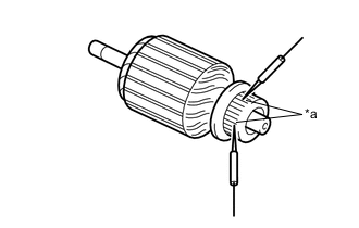
*a Segment Check the commutator for an open circuit.
-
Measure the resistance according to the value(s) in the table below.
Standard Resistance Tester Connection Condition Specified Condition Segment - Segment Always Below 1 Ω If the result is not as specified, replace the starter armature assembly.
-
-
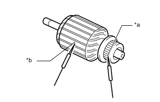
*a Segment *b Starter Armature Core Check the commutator for a short circuit.
-
Measure the resistance according to the value(s) in the table below.
Standard Resistance Tester Connection Condition Specified Condition Segment - Starter armature core Always 10 kΩ or higher If the result is not as specified, replace the starter armature assembly.
-
-
Check the commutator appearance.
If the surface is dirty or burnt, replace the starter armature assembly.
-
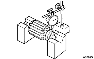
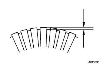
Check the commutator for runout.
-
Place the commutator on V-blocks.
-
Using a dial indicator, measure the runout.
Maximum runout 0.05 mm (0.00197 in.) If the runout is more than the maximum, replace the starter armature assembly.
-
-
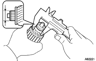
Using a vernier caliper, measure the commutator diameter.
Standard diameter 29 mm (convex part) (1.14 in.) Minimum diameter 28 mm (convex part) (1.10 in.) If the diameter is less than the minimum, replace the starter armature assembly.
-
Check that the undercut portion between the segments is free of foreign matter and measure its depth.
Standard undercut depth 0.7 mm (convex part) (0.0276 in.) Minimum undercut depth 0.4 mm (convex part) (0.0157 in.) If the undercut depth is less than the minimum, adjust it with a hacksaw blade.
-
-
INSPECT STARTER BRUSH HOLDER ASSEMBLY
-
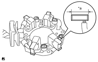
*a Length Check the brush length.
-
Using a vernier caliper, measure the brush length.
Standard length 14.4 mm (0.567 in.) Minimum length 9 mm (convex part) (0.354 in.) If the length is less than the minimum, replace the starter brush holder assembly.
-
-
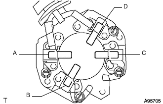
Check the starter brush holder assembly resistance.
-
Measure the resistance according to the value(s) in the table below.
Standard Resistance Tester Connection Condition Specified Condition A - B
A - C
B - D
C - D
Always 10 kΩ or higher A - D
B - C
Below 1 Ω If the result is not as specified, replace the starter brush holder assembly.
-
-
Check the brush spring load.
-
Take a pull scale reading the instant the brush spring separates from the brush.
Standard spring load 22 to 27 N (2 to 3 kgf, 4.9 to 6.1 lbf) Minimum spring load 14 N (1 kgf, 3.1 lbf) If the spring load is less than the minimum, replace the starter brush holder assembly.
-
-
-
INSPECT STARTER CENTER BEARING CLUTCH SUB-ASSEMBLY
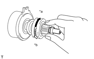
*a Free *b Lock
-
Check the clutch pinion gear.
-
While holding the starter center bearing clutch sub-assembly, rotate the clutch pinion gear clockwise, and check that it turns freely. Try to rotate the clutch pinion gear counterclockwise and check that it locks.
If the clutch pinion gear does not operate as specified, replace the starter center bearing clutch sub-assembly.
-
-
-
INSPECT REPAIR SERVICE STARTER KIT (for CVT)
-
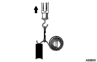
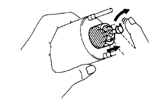
Check the plunger.
-
Push in the plunger and check that it returns quickly to its original position.
Note
-
To avoid damaging the inside of the magnet switch, do not release the plunger quickly.
-
Do not drop the plunger.
If necessary, replace the repair service starter kit.
-
-
-
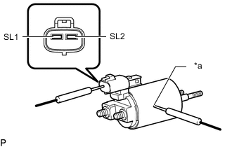
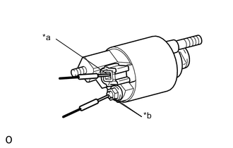
*a Magnet Switch Body Check the repair service starter kit resistance.
-
Measure the resistance according to the value(s) in the table below.
Standard Resistance Tester Connection Condition Specified Condition Terminal SL1 - Magnet switch body Always Below 1 Ω Terminal SL2 - Magnet switch body Below 2 Ω If the result is not as specified, replace the repair service starter kit.
-
-
-
INSPECT MAGNET STARTER SWITCH ASSEMBLY (for Manual Transaxle)
-
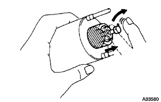
Check the plunger.
-
Push in the plunger and check that it returns quickly to its original position.
If necessary, replace the magnet starter switch assembly.
-
-
*a Terminal 50 *b Terminal C Check the pull-in coil for an open circuit.
-
Measure the resistance according to the value(s) in the table below.
Standard Resistance Tester Connection Condition Specified Condition Terminal 50 - Body Always Below 1 Ω If the result is not as specified, replace the magnet starter switch assembly.
-
-
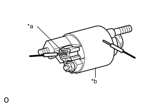
*a Terminal 50 *b Magnet Starter Switch Body Check whether the holding coil has an open circuit.
-
Measure the resistance according to the value(s) in the table below.
Standard Resistance Tester Connection Condition Specified Condition Terminal 50 - Body Always Below 2 Ω If the result is not as specified, replace the magnet starter switch assembly.
-
-