ВПУСКНОЙ КОЛЛЕКТОР УСТАНОВКА
CAUTION / NOTICE / HINT
Note
-
When replacing the injectors (including shuffling the injectors between the cylinders), common rail, intake manifold or cylinder head, it is necessary to replace the injection pipes with new ones.
-
When replacing the fuel supply pump, common rail, intake manifold or cylinder head, it is necessary to replace the fuel inlet pipe with a new one.
PROCEDURE
-
INSTALL STUD BOLT
Tech Tips
If a stud bolt is deformed or the threads are damaged, replace it.
-
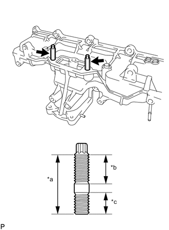
*a 35 mm (1.38 in.) *b 20 mm (0.787 in.) *c 13 mm (0.512 in.) Using an E8 "TORX" wrench, install the 2 stud bolts.
- Torque:
- 9.0 N*m { 92 kgf*cm, 80 in.*lbf }
-
-
INSTALL INTAKE MANIFOLD
-
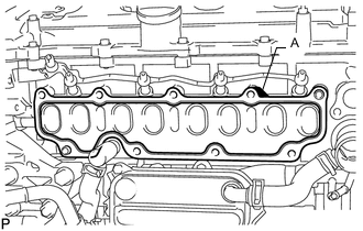
Install a new gasket to the cylinder head.
Tech Tips
Install the gasket with the part labeled A facing the right side of the vehicle as shown in the illustration.
-
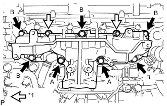
*1 Nut Install the intake manifold with the 7 bolts and 2 nuts.
- Torque:
- 23 N*m { 235 kgf*cm, 17 ft.*lbf }
Bolt Length Item Length Bolt A 90 mm (3.54 in.) Bolt B 25 mm (0.984 in.)
-
-
CONNECT NO. 2 VACUUM TRANSMITTING HOSE ASSEMBLY
-
Connect the No. 2 vacuum transmitting hose assembly to the intake manifold, and slide the clamp to secure the hose.
-
-
INSTALL NO. 2 INTAKE MANIFOLD
-
Install a new gasket and the No. 2 intake manifold with the bolt and 2 nuts.
- Torque:
- 24 N*m { 245 kgf*cm, 18 ft.*lbf }
-
-
INSTALL ENGINE COVER BRACKET
-
Install the engine cover bracket with the bolt.
- Torque:
- 20 N*m { 204 kgf*cm, 15 ft.*lbf }
-
-
INSTALL GAS FILTER BRACKET
-
Install the gas filter bracket with the 2 bolts.
- Torque:
- 8.8 N*m { 90 kgf*cm, 78 in.*lbf }
-
-
INSTALL NO. 1 GAS FILTER
-
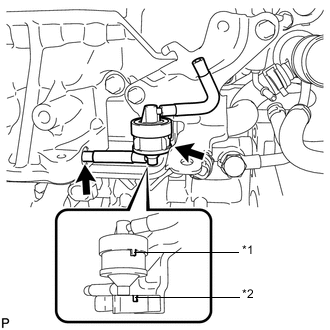
*1 Protrusion *2 Groove Install the No. 1 gas filter to the gas filter bracket.
Note
Make sure the protrusion of the No. 1 gas filter is aligned with the groove of the gas filter bracket.
-
Connect the vacuum hose.
-
-
INSTALL DIESEL TURBO PRESSURE SENSOR
-
INSTALL ENGINE OIL LEVEL DIPSTICK GUIDE
-
Install a new O-ring to the engine oil level dipstick guide.
-
Install the engine oil level dipstick guide with the 2 bolts.
- Torque:
- 24 N*m { 245 kgf*cm, 18 ft.*lbf }
-
Connect the connector and attach the wire harness clamp to the engine oil level dipstick guide.
-
Install the engine oil level dipstick.
-
-
INSTALL INTAKE MANIFOLD INSULATOR
-
Install the intake manifold insulator to the intake manifold.
-
-
INSTALL COMMON RAIL ASSEMBLY
-
INSTALL INJECTION PIPE SUB-ASSEMBLY
-
INSTALL FUEL INLET PIPE SUB-ASSEMBLY
-
INSTALL ELECTRIC EGR CONTROL VALVE ASSEMBLY
-
INSTALL NO. 2 EGR PIPE SUB-ASSEMBLY
-
CONNECT NO. 8 WATER BY-PASS HOSE
-
INSTALL NO. 7 WATER BY-PASS HOSE
-
Install the No. 7 water by-pass hose to the electric EGR control valve assembly, and slide the clamp to secure the hose.
-
-
INSTALL EGR VALVE BRACKET
-
CONNECT ENGINE WIRE
-
INSTALL DIESEL THROTTLE BODY ASSEMBLY
-
CONNECT CABLE TO NEGATIVE BATTERY TERMINAL
Note
When disconnecting the cable, some systems need to be initialized after the cable is reconnected.
-
BLEED AIR FROM FUEL SYSTEM
-
INSPECT FOR FUEL LEAK