ОХЛАДИТЕЛЬ РОГ СНЯТИЕ
PROCEDURE
-
PRECAUTION
Note
After turning the ignition switch off, waiting time may be required before disconnecting the cable from the battery terminal. Therefore, make sure to read the disconnecting the cable from the battery terminal notices before proceeding with work.
-
DISCONNECT CABLE FROM NEGATIVE BATTERY TERMINAL
Note
When disconnecting the cable, some systems need to be initialized after the cable is reconnected.
-
DISCONNECT CABLE FROM POSITIVE BATTERY TERMINAL
-
REMOVE NO. 1 ENGINE COVER
-
REMOVE NO. 1 ENGINE UNDER COVER
-
DRAIN ENGINE COOLANT
-
REMOVE BATTERY CLAMP SUB-ASSEMBLY
-
REMOVE BATTERY INSULATOR
-
REMOVE BATTERY
-
REMOVE BATTERY TRAY
-
REMOVE BATTERY CARRIER ASSEMBLY
-
REMOVE BATTERY BRACKET REINFORCEMENT
-
REMOVE AIR CLEANER CAP SUB-ASSEMBLY WITH AIR CLEANER HOSE ASSEMBLY
-
REMOVE AIR CLEANER FILTER ELEMENT SUB-ASSEMBLY
-
REMOVE AIR CLEANER CASE SUB-ASSEMBLY
-
DISCONNECT COMPRESSOR OUTLET ELBOW
-
DISCONNECT ENGINE WIRE
-
REMOVE NO. 4 WATER BY-PASS HOSE
-
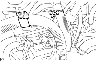
DISCONNECT NO. 1 AIR TUBE ASSEMBLY
-
DISCONNECT FUEL FEED PIPE SUB-ASSEMBLY
-
Detach the 2 clamps and disconnect the engine wire.
-
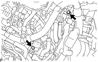
Remove the 2 bolts and disconnect the fuel feed pipe sub-assembly.
-
Disconnect the vacuum hose from the No. 2 fuel hose.
-
Disconnect the fuel feed pipe sub-assembly from the fuel pipe clamp.
-
-
REMOVE NO. 1 TURBO INSULATOR
-
REMOVE NO. 1 EXHAUST MANIFOLD HEAT INSULATOR
-
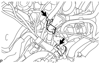
Disconnect the air fuel ratio sensor connector.
-
Raise the air fuel ratio sensor connector to remove the air fuel ratio sensor connector from the bracket.
-
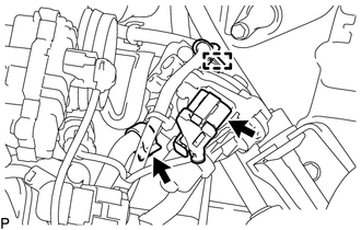
Detach the 2 clamps and disconnect the air fuel ratio sensor.
-
Detach the 2 clamps and disconnect the engine wire.
-
Remove the 2 bolts and No. 1 exhaust manifold heat insulator.
-
-
REMOVE EGR COOLER ASSEMBLY WITH EGR VALVE ASSEMBLY
-
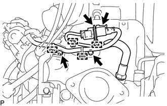
Disconnect the EGR valve assembly connector.
-
Detach the clamp and disconnect the engine wire from the EGR valve assembly.
-
Disconnect the hose clamp from the EGR cooler hose.
-
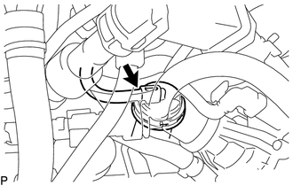
Disconnect the vacuum hose from the EGR cooler assembly.
-
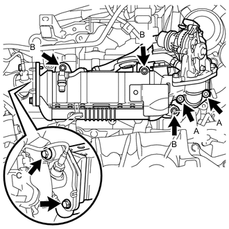
Remove the 7 bolts and EGR cooler assembly with EGR valve assembly.
Tech Tips
-
When removing the bolts (A), use a T45 "TORX" socket wrench.
-
When removing the bolts (B), use a 6 mm hexagon wrench.
-
The bolt (C) in the illustration cannot be removed from the intake manifold.
-
-
Remove the gasket.
-
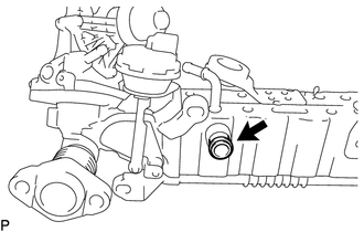
Remove the water pipe from the EGR cooler assembly.
-
-
REMOVE EGR VALVE ASSEMBLY