ТОПЛИВНАЯ ФОРСУНКА СНЯТИЕ
PROCEDURE
-
PRECAUTION
Note
-
After the engine has stopped, wait at least 1 minute before releasing the high pressure lines.
-
When working on the fuel circuit, protect the generator assembly against contamination. Cover the generator assembly with suitable materials. Failure to comply with this procedure may result in a generator assembly malfunction.
-
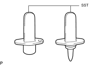
After disconnecting the pressure line, it is absolutely essential to seal the injector assemblies and the common rail assembly with SST.
SST PZ4TB-04941-79 -
After turning the ignition switch off, waiting time may be required before disconnecting the cable from the negative (-) battery terminal. Therefore, make sure to read the disconnecting the cable from the negative (-) battery terminal notices before proceeding with work.
-
-
DISCONNECT CABLE FROM NEGATIVE BATTERY TERMINAL
Note
When disconnecting the cable, some systems need to be initialized after the cable is reconnected.
-
REMOVE NO. 1 ENGINE COVER
-
REMOVE ENGINE COVER
-
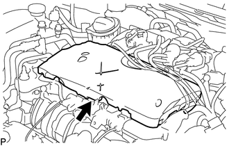
Remove the engine cover.
-
-
REMOVE INJECTION PIPE SUB-ASSEMBLY
Note
Reset SST in a timely manner to prevent bending of pressure lines.
-
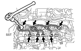
Using SST, loosen the 4 union nuts at the common rail assembly end of the 2 No. 1 injection pipe sub-assemblies and 2 No. 2 injection pipe sub-assemblies.
SST PZ4TB-04959-10 -
Using SST, loosen the 4 union nuts at the 4 injector assembly ends of the 2 No. 1 injection pipe sub-assemblies and 2 No. 2 injection pipe sub-assemblies.
SST PZ4TB-04959-10 -
Remove the 2 No. 1 injection pipe sub-assemblies and 2 No. 2 injection pipe sub-assemblies.
-
-
REMOVE CAMSHAFT POSITION SENSOR
-
DISCONNECT NOZZLE LEAKAGE PIPE ASSEMBLY
-
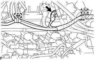
Disconnect the connector and detach the 2 clamps to disconnect the wire harness.
-
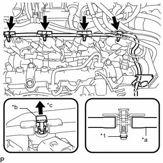
*1 Sealing Ring *a Leakage Line *b Clip *c Pull up Pull up the 4 clips and disconnect the nozzle leakage pipe assembly from the 4 injector assemblies as shown in the illustration.
Note
If a sealing ring is damaged, the entire leakage line must be replaced.
-
Remove the 4 sealing rings from the nozzle leakage pipe assembly.
-
-
REMOVE INJECTOR ASSEMBLY
-
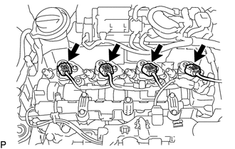
Disconnect the 4 injector assembly connectors.
-
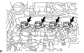
Using an E10 "TORX" socket wrench, remove the 4 bolts and 4 centering rings.
-
Remove the 4 clamping claws from the 4 injector assemblies.
-
Remove the 4 injector assemblies from the cylinder head cover sub-assembly.
-
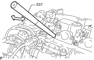
Pull out the injector assembly with light rotational movements.
SST PZ4TB-04942-79 Tech Tips
-
If an injector assembly is stuck tight, mount SST (rod) to the pressure line connection.
-
Move the injector assembly with SST (rod) only by a few degrees.
-
-
-