ТОПЛИВНЫЙ БАК УСТАНОВКА
PROCEDURE
-
INSTALL FUEL SENDER GAUGE ASSEMBLY
-
INSTALL FUEL TUBE GROMMET
-
Install the 3 fuel tube grommets to the fuel tank assembly.
-
-
INSTALL FUEL TUBE CLAMP NO.3
-
Install the No. 3 fuel tube clamp to the fuel tank assembly.
-
-
INSTALL NO. 5 FUEL TUBE CLAMP
-
Install the No. 5 fuel tube clamp to the fuel tank assembly.
-
-
INSTALL NO. 2 FUEL MAIN TUBE SUB-ASSEMBLY (w/ Combustion Type Power Heater)
-
Install the No. 2 fuel tank main tube sub-assembly to the No. 3 fuel tube clamp, No. 5 fuel tube clamp and 3 fuel tube grommets.
-
-
INSTALL FUEL TANK RETURN TUBE
-
Install the fuel return tube to the No. 3 fuel tube clamp, No. 5 fuel tube clamp and 3 fuel tube grommets.
-
-
INSTALL FUEL TANK MAIN TUBE SUB-ASSEMBLY
-
Install the fuel tank main tube sub-assembly to the No. 3 fuel tube clamp, No. 5 fuel tube clamp and 3 fuel tube grommets.
-
-
INSTALL FUEL SUCTION WITH PUMP AND GAUGE TUBE ASSEMBLY
-
Install a new gasket onto the fuel suction with pump and gauge tube assembly.
-
Install the fuel suction with pump and gauge tube assembly.
Note
Do not damage the fuel suction with pump and gauge tube assembly.
-
-
INSTALL FUEL TANK VENT TUBE SET PLATE
-
Install the fuel tank vent tube set plate with the 8 bolts.
- Torque:
- 6.0 N*m { 61 kgf*cm, 53 in.*lbf }
-
-
CONNECT FUEL TANK MAIN TUBE SUB-ASSEMBLY
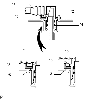
*1 Fuel Tube *2 Fuel Tube Joint *3 Tube Joint Clip *4 O-Ring *5 Collar *a CORRECT *b INCORRECT
-
Push the fuel tube joint into the plug of the fuel suction with pump and gauge tube assembly, and then install the tube joint clip.
Note
-
Check that there are no scratches or foreign objects on the connecting parts.
-
Check that the fuel tube joint is inserted securely.
-
Check that the fuel tube joint clip is on the collar of the fuel tube joint.
-
After installing the tube joint clip, check that the fuel tube joint cannot be pulled off.
-
Be careful not to damage any clip. If a clip is damaged, replace it.
-
-
-
CONNECT FUEL TANK RETURN TUBE
-
*1 Fuel Tube *2 Fuel Tube Joint *3 Tube Joint Clip *4 O-Ring *5 Collar *a CORRECT *b INCORRECT Push the fuel tube joint into the plug of the fuel suction with pump and gauge tube assembly, and then install the tube joint clip.
Note
-
Check that there are no scratches or foreign objects on the connecting parts.
-
Check that the fuel tube joint is inserted securely.
-
Check that the fuel tube joint clip is on the collar of the fuel tube joint.
-
After installing the tube joint clip, check that the fuel tube joint cannot be pulled off.
-
Be careful not to damage any clip. If a clip is damaged, replace it.
-
-
-
CONNECT NO. 2 FUEL MAIN TUBE SUB-ASSEMBLY (w/ Combustion Type Power Heater)
*1 Fuel Tube *2 Fuel Tube Joint *3 Tube Joint Clip *4 O-Ring *5 Collar *a CORRECT *b INCORRECT
-
Push the fuel tube joint into the plug of the fuel suction with pump and gauge tube assembly, and then install the tube joint clip.
Note
-
Check that there are no scratches or foreign objects on the connecting parts.
-
Check that the fuel tube joint is inserted securely.
-
Check that the fuel tube joint clip is on the collar of the fuel tube joint.
-
After installing the tube joint clip, check that the fuel tube joint cannot be pulled off.
-
Be careful not to damage any clip. If a clip is damaged, replace it.
-
-
-
INSTALL FUEL EMISSION HOSE
-
Attach the clamp and install the fuel emission hose.
-
-
INSTALL FUEL TANK ASSEMBLY
-
Set the fuel tank assembly on an engine lifter.
-
Lift up the engine lifter.
-
Connect the fuel sender gauge connector.
Note
Be careful not to cut the wire harness.
-
Connect the wire harness to the 2 fuel tube grommets.
-
Install the No. 1 fuel tank band sub-assembly with the 2 bolts.
- Torque:
- 45 N*m { 459 kgf*cm, 33 ft.*lbf }
-
Install the No. 1 fuel tank band sub-assembly LH with the 2 bolts.
- Torque:
- 45 N*m { 459 kgf*cm, 33 ft.*lbf }
-
Install the No. 2 fuel tank band sub-assembly with the 2 bolts.
- Torque:
- 45 N*m { 459 kgf*cm, 33 ft.*lbf }
-
-
CONNECT FUEL TANK BREATHER HOSE
-
Connect the fuel tank breather hose to the fuel tank assembly.
-
-
CONNECT FUEL TANK TO FILLER PIPE HOSE
-
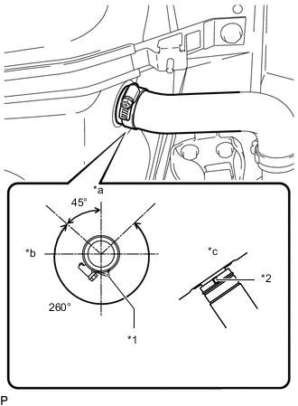
*1 Stopper *2 Protrusion *a Top *b Front *c Bottom of Fuel Tank Connect the fuel tank to filler pipe hose to the fuel tank assembly and tighten the hose clamp.
Tech Tips
Make sure the hose clamp is oriented as shown in the illustration.
-
-
CONNECT FUEL TANK MAIN TUBE SUB-ASSEMBLY
-
Connect the fuel tank main tube sub-assembly to the fuel pipe.
-
-
CONNECT FUEL TANK RETURN TUBE
-
Connect the fuel tank return tube to the fuel pipe, and slide the clamp to secure the hose.
-
-
CONNECT NO. 2 FUEL MAIN TUBE SUB-ASSEMBLY (w/ Combustion Type Power Heater)
-
Connect the No. 2 fuel main tube sub-assembly to the fuel pipe, and slide the clamp to secure the hose.
-
-
CONNECT NO. 2 PARKING BRAKE CABLE ASSEMBLY
-
Connect the No. 2 parking brake cable assembly with the 2 bolts.
- Torque:
- 6.0 N*m { 61 kgf*cm, 53 in.*lbf }
-
-
INSTALL NO. 1 FLOOR UNDER COVER
-
Attach the 2 clips and install the No. 1 floor under cover with the 2 nuts.
-
-
INSTALL NO. 1 FUEL TANK PROTECTOR
-
Attach the 3 clips and install the No. 1 fuel tank protector with the nut.
- Torque:
- 20 N*m { 204 kgf*cm, 15 ft.*lbf }
-
-
INSTALL FRONT FLOOR COVER
-
Install the front floor cover with the bolt and nut.
- Torque:
- for bolt
- 12 N*m { 122 kgf*cm, 9 ft.*lbf }
- for nut
- 6.0 N*m { 61 kgf*cm, 53 in.*lbf }
-
Attach the 5 clips.
-
-
INSPECT FOR FUEL LEAK